When starting Define Component on a Cap Screw or a Nut in a 3DPart, Create Feature lets you automatically create
the Axis systems and Assembly Features
Drill Hole and Tap Hole, as follows.
- Screw with a cylinder head
- Three axis system features are created (Top, bottom, and middle).
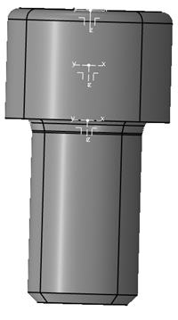
The
top axis system becomes the Hook.
- Drill Hole
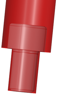
- Tap Hole
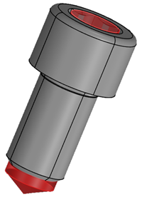
- Screw with countersunk head
- Only the axis system on the top of the head cone is created
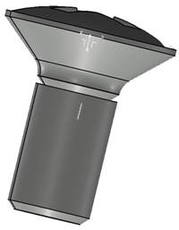
- Drill Hole: The angle of the cone is the same as the angle of the cone of the screw.
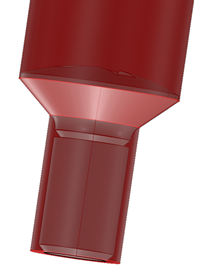
- Tap Hole
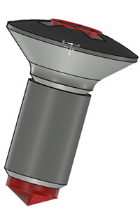
- Screw with hexagonal head
- Three axis system features are created (Top, bottom, and middle)
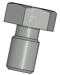
The
top axis system becomes the Hook
- Drill Hole
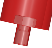
- Tap Hole
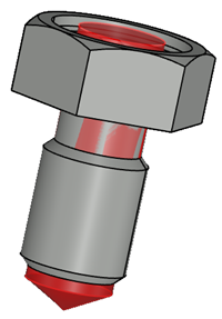
- Screw with any head
- Three axis system features are created (Top, bottom, and middle).
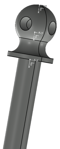
The top axis system becomes the Hook.
- Drill Hole

- Tap Hole

- Specific case where the guide diameter (in blue) is larger than the thread diameter
(orange)
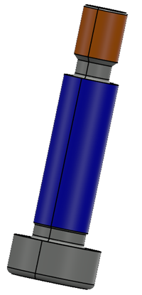
- Three axis system features are created (Top, bottom, and middle).
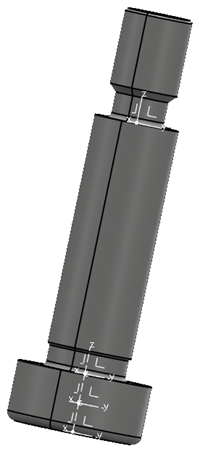
The top axis system becomes the Hook.
- Drill Hole stops on the bottom plane of the guide
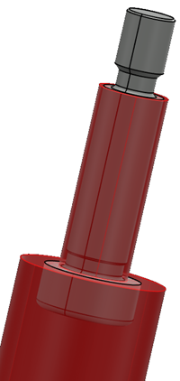
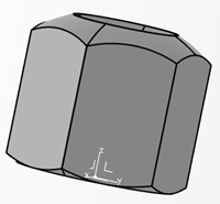
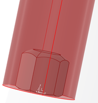
- Nut: For all cases, only the Hook and the Drill Hole are created.
Note:
Screws without heads are not supported.


