Create Joined Elements
-
From the Check and Repair
section of the action bar, click Join
 . .
- Select the surfaces or curves to be joined in the work area or in the tree.
The selected elements are added to the Elements to Join
list. You can activate Add Mode
 ,
Remove Mode ,
Remove Mode
 ,
or Both Mode ,
or Both Mode
 options.
- To add a line at the end of the rows in the table, click
 . .
- To remove all lines in the table, click
 . .
-
Alternatively
-
Select the elements to join.
-
Click Join
in the context toolbar.
-
Double-click Join.x feature in the tree to open the Join dialog box.
- You can edit the Elements to Join list as follows:
- Click a selected element in the work area to cancel the selection and remove it from the list.
- Right-click the elements in the list and select Clear Selection to
cancel the selection of all elements.
- Select one element in the list, right-click, and select Replace
Selection. Then select another element in the work area to replace the element in the list.
- Double-click the required mode to activate it permanently.
- Right-click the elements from the list and
select Check Selection.
This lets you verify whether an element to be joined presents any intersection (that is,
topological errors) with other elements before creating the joined
surface. The Checker dialog box is displayed,
containing the list of domains (that is, sets of connected cells)
belonging to the selected elements from the Elements To
Join list. - Click Preview.
Self-intersections detected are displayed on the geometry in the work area.

-
Click Cancel to return to the
Join box.
-
Right-click the elements and choose the propagation options to allow the
selection of elements with the same dimension.
- Distance Propagation: the tolerance
corresponds to the Merging distance
value.
- Angular Propagation: the tolerance
corresponds to the Angular Threshold value,
if defined. Otherwise, it corresponds to the G1 tolerance value as
defined in the part.
For more information about Distance
Propagation and Angular
Propagation, see Using the Check Options.
Each new element found by propagation of the selected elements is
highlighted and added to the Elements To Join
list.
-
Click Preview in the Join
dialog box.
The joined element is previewed and its orientation displayed.
Click the arrow to invert it if required. 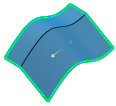 The join is
oriented according to the first element in the list. If you change this
element, the join's orientation is automatically set to match the
orientation of the new topmost element in the list.
Using the Check Options
-
Select the Tangency check box to check whether the
transitions between the elements are tangent continuous.
If they are not, an error message is issued when you click
Preview advising you to modify the selected
inputs. The elements in error are highlighted in the 3D geometry once
you have clicked OK in the Update
Error dialog box:

-
Select the Check connectivity check box to check
whether the elements to be joined are connected.
If they are not, an error message is issued indicating the number of
connected domains in the resulting join and elements in error are
highlighted in the 3D geometry.
-
Select the Check manifold check box to find out whether the resulting join is manifold.
-
Expand Advanced.
-
Select the Simplify the result check box to allow the system to automatically reduce the number of elements (faces or edges) in the resulting join whenever possible.
-
Select the Ignore erroneous elements check box to let the system ignore surfaces and edges that would not allow the join to be created.
-
You can also set the tolerance at which two elements are considered as being only one using the Merging distance.
-
Select Heal merged cells for topologically healing the joined elements.
This option uses the tolerance value specified in the Merging
Distance box.
-
Expand Tolerant Modeling.
-
In the Merging Distance box, specify the required
value.
-
Select the Angular Threshold check box and specify
the angle value below which the elements are to be joined.
Removing Sub-Elements
-
Click the Sub-Elements To Remove box to display the
list of sub-elements in the join.
These sub-elements are elements making up the elements selected to
create the join, such as separate faces of a surface, for example for, that
are to be removed from the join being created. You can edit the
sub-elements list as described above (in step 3) for the list of
elements to be joined. -
Select the Create join with sub-elements check box
to create a second join of all sub-elements displayed in the list that are
not to be joined in the first join.
-
Click OK to create the joined surface or curve.
The surface or curve (identified as Join.xxx) is added to the tree.
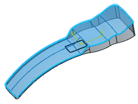
Create a Federation
You can hybrid combine several elements to a federation. The combined
elements are treated as a single element. You cannot select the elements of a
federation individually in the work area.
This is especially useful when modifying linked geometry to avoid re-specifying all input elements.
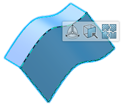
Before you begin: Open a 3DShape with several surfaces and a sketch. 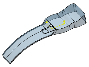
-
Add all surfaces to the Elements to join list.
-
Expand Advanced.
-
From the Propagation Mode list, select
Tangent continuity.
The system automatically selects the elements making up the federation,
taking this propagation mode into account. You can optionally select on
of the followingP:
- No federation: no element can be
selected
- All: adds all elements of the join feature to
the federation. Selection is disabled.
- Point continuity
Tangent continuity: adds all elements with
the defined transition.
- Tangent continuity: all elements tangent to
the selected element are part of the federation. Only the top faces
of the joined surface are detected, not the lateral faces.
- No propagation: adds only the elements
explicitly selected to the federation.
You can edit the Elements to join list as
described in Joining Curves or Surfaces.
-
Select the surfaces to be added, to the federation.
-
Click OK to create the join.
Use the Federation Capability
-
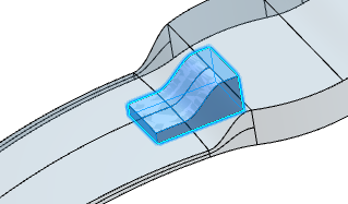
Move to the Part Design
app, select the sketch and click Pad
 in the Model section of the action bar to create an Up to surface pad, using the joined surface as the limiting surface. in the Model section of the action bar to create an Up to surface pad, using the joined surface as the limiting surface.
-
Select the upper front edge of the pad.
-
Click Edge Fillet
 in the Refine section of the action bar and create a 2mm fillet. in the Refine section of the action bar and create a 2mm fillet.
-
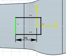
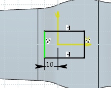
Double-click the sketch from the tree, click the constraint on the sketch to change it to 10mm
in the box.
The sketch is now lying over one face only.
| before modification |
after modification |
 |
 |
-
Click
 to exit the Sketcher
app. to exit the Sketcher
app.
The pad can automatically be recomputed, because the faces are combined to a federation and treated as a single element. 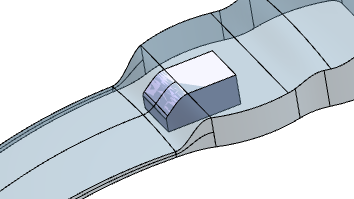 -
Double-click the join, select No propagation mode in
the Join dialog box and click
OK.
-
Click OK in the Join dialog
box.
A message is displayed indicating the edge no longer recognized on
the pad.
-
Click OK.
The Update Diagnosis dialog box is displayed,
allowing you to re-enter the specifications the edge and its fillet. You
then need to edit the edge and redo the fillet to obtain the previous pad up
to the joined surface.
-
Select the line indicating the lost edge and click Edit.
-
Click OK in the Edit dialog box showing the lost edge in the Selected element box.
The fillet is recomputed based on the correct edge.
Remove Lost Edges automatically
If elements of a join feature have been replaced, you can remove them from the Elements to join list in one step.
Before you begin: Open a part with a join feature, for example consisting of two faces of a rectangular volume created from a sketch. 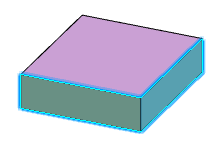
-
In the tree, double-click the sketch, delete the geometry, create a circle instead, and exit the Sketcher
app.
The Pad is recomputed and the Update Diagnosis dialog box opens. Edges that are no longer recognized on the pad appear in the work area. 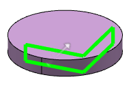 -
Select the first line and click Edit.
The Feature Definition Error panel appears. Do one of the following:
- Click Yes to remove all deleted sub-elements from the Elements To Join list and select the sub-elements again.
- Click No to preserve them and be able to edit them manually.
|