Create a Midsurface from Face Pairs
You can create a midsurface from a pair of faces.
-
,From the
Idealize section of the
action bar, click Midsurface
 . .
-
In the Support box, select the solid feature, volume feature or body.
- In the Creation Mode list, select Face Pairs.
-
Select one or more pairs of faces from which the midsurface will be extracted.
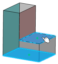
The selected face pairs appear in the Midsurface Definition dialog box, under the Main Side and Other Side columns.
-
In the Offset ratio box, type the offset value or use the arrows to change the value.
-
Click OK.
Create a Midsurface by Offsetting Faces (Non-Associative Offset)
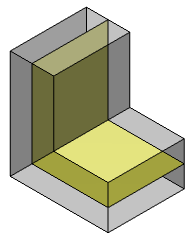
You can create a midsurface from a set of faces (or extract features) and an offset. This is useful for complex models which may not contain parallel faces to form a pair. The created midsurface is automatically extrapolated and re-limited to the selected support.
-
In the Support box, select a solid feature, volume feature or a body.
-
In the Creation Mode list, select Faces to Offset.
-
In the Faces To Offset box, select either the faces to offset or the extract features.
- Face selection: Select one or more faces in the work area.
- Extract feature selection: Perform one of the following actions from the context menu:
- Select . The Extract Definition dialog box appears. For more information, refer to Extracting Elements.
- Select . Then, select one or more faces in the work area.
- Select . For more information, refer to Extracting Sub-Elements.
-
In the Computation Mode list, select Manual.
-
Click Compute Offset
 beside the Offset box. beside the Offset box.
- Offset faces from the selected faces are detected.
- Minimum and maximum offset values are computed and displayed in the work area with the Min and Max indicators.
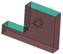
- Average offset value is computed and displayed in the Offset box.
- Optional:
Click Min or Max indicator in the work area to evaluate the offset parameter.
The value in the Offset box is refreshed accordingly.
- Optional:
Right-click Min or Max indicator in the work area and select Remove Min or Remove Max, respectively from the context menu.
The Min or Max indicators are removed from the current face. They re-appear on the next sequential face with the recomputed Min or Max value. Note:
The indicators do not appear after they are removed from the last face.
-
In the Offset ratio box, type the offset value or use the arrows to change the value.
-
Click OK.
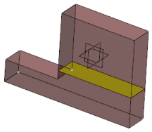
The midsurface is generated.
Create a Midsurface by Offsetting Faces (Associative Offset)
You can create a midsurface from a set of faces (or extract features) and an associative offset.
-
In the Support box, select a solid feature, a volume feature or a body.
-
In the Creation Mode list, select Faces to Offset.
-
In the Faces To Offset box, select either the faces to offset or the extract features.
-
In the Computation Mode list, select Automatic.
This mode uses five rays to compute the offset faces: four rays projected from each corner of the selected face and one from the center.
-
In the Computation Method list, select one of the following options:
-
Maximum takes only the maximum applicable offset faces into account.
-
Minimum takes only the minimum applicable offset faces into account.
-
Average takes the average of applicable offset faces into account.
-
Specify a Thickness Threshold.
The thickness threshold is a length parameter. It represents the maximum distance from the selected faces under which the offset faces are considered for computation. 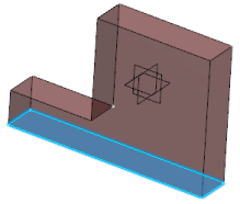 -
In the Offset ratio box, type the offset value or use the arrows to change the value.
-
Click OK.
The midsurface is generated. 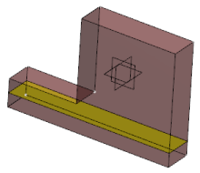 -
Vary the Thickness Threshold and click OK.
The midsurface is generated at another position. 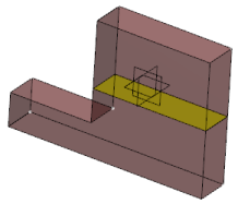
Create a Midsurface Using a Thickness Threshold
You can create a midsurface according to a thickness threshold.
-
In the Creation Mode list, select Automatic.
-
In the Support box, select a solid feature, a volume feature, or a body.
An automatic threshold value representing the maximum thickness value appears in the Thickness Threshold box. By default, the Automatic Thickness Threshold check box is selected, and the value is not editable. -
Click OK.
The midsurface is generated. 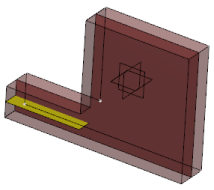 - Optional:
Click OK.
The midsurfaces are generated.
Create a Midsurface from Ribs
You can create a midsurface from ribs using an existing connected midsurface.
-
Define the main shell midsurface by following the steps from 1 through 7 from Create a Midsurface from Face Pairs.
-
Select the Create a new rib midsurface after OK check box.
-
Click OK.
The Midsurface Definition dialog box appears again with Limiting midsurface box containing the main shell midsurface.
-
Select the required mode of midsurface creation in the Creation Mode list.
-
Depending on the mode you selected (either Face Pairs or Faces to Offset), follow the steps from the appropriate tasks above to select the faces from the rib.
-
Click OK.
The rib midsurface is generated with the main shell midsurface acting as a relimiter.
|
 .
.


