The Tree | ||
| ||
Tree Structure
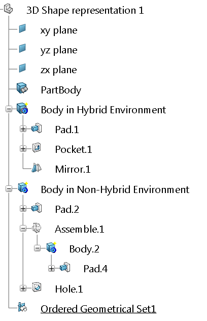
The following picture represents a typical Part Designtree
Symbols
The various symbols used to identify the elements created in the tree are described in this reference section.
 |
3D Shape Representation |

|
Body |  | Text with Leader |

|
Geometrical Set |  | Flag Note with Leader |
 | Ordered Geometrical Set |  | View From Reference |
- The gear icon masks the Body icon when Enable hybrid design inside part bodies and bodies option is cleared.
- The gear icon masks the Part Body icon
 when Enable hybrid design inside part bodies and bodies option is selected.
 |
Pad |
 | Groove |
 |
 | Hole | |
 | Drafted Filleted Pad |
 | Rib |
 | Drafted Filleted Pocket |
 | Slot |
 | Shaft |
 | Stiffener |
 |
Multi-Pad |
 | Multi-sections Solid |
 |
Multi-Pocket |
 | Removed Multi-sections Solid |
 |
Edge Fillet |
 | Variable Angle Draft |
 |
Variable Fillet |
 | Advanced Draft |
 |
Face-Face Fillet | Draft Both Sides | |
 | Tritangent Fillet |  | Auto Draft |
 | Chordal Fillet |
 | Remove Face |
 | Auto Fillet |
 | Shell |
 | Chamfer |
 | Thickness |
 | Draft |
 | Thread/Tap |
 | Draft from Reflect Lines |
 | Replace Face |
 | Split |  |
Close Surface |
 | Thick Surface |  |
Sew Surface |
|
|
Translation |
 | Circular Pattern |
 |
Rotation |  | User Pattern |
 |
Symmetry |
 | User Pattern |
|
| Mirror |
 | Scaling |
 | Affinity |
 | Axis To Axis |
 | Rectangular Pattern |
 |
Point |  | Plane |
 |
Line |
 |
Assemble |
 | Intersect |
 |
Add |
 | Union Trim |
 |
Remove |
 | Remove Lump |
 |
Sketch |
 |
All Types of Constraint |
 |
Draft Analysis |  | Surface Curvature Analysis |
 |
Axis System |  | User Feature |
|
|
Power Copy |