Creating Grooves | |||||
|
| ||||
-
From the Model or the Essentials
section of the action bar, click Groove
 .
.
-
In the
Selection box of the
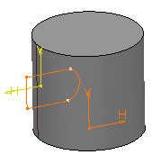
Groove.x dialog box, select the required
profile or surface.

-
In the Axis box, select the axis to create a groove
about it.
If the profile and the axis belongs to the same sketch, axis gets selected automatically.
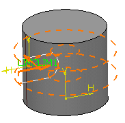
The preview of a groove appears about the axis. The two limits, LIM1 (corresponds to the first angle value) and LIM2 (corresponds to the second angle value) appear.

-
From the list, select the limiting Type among the following and
define the limiting element:
- Angle: Creates a feature up to the defined angle value.
- Up to next: Creates a feature up to thenext intersecting feature.
- Up to last: Creates a feature up to the last intersecting feature.
- Up to plane: Creates a feature up to the the defined plane.
- Up to surface: Creates a feature up to the the defined surface.
The preview of the groove in the first direction is displayed. - Optional:
Under Second Limit, from the list, select the limiting
type among the following and define the limiting element:
- Angle: Creates a feature up to the defined angle value.
- Up to next: Creates a feature up to thenext intersecting feature.
- Up to last: Creates a feature up to the last intersecting feature.
- Up to plane: Creates a feature up to the the defined plane.
- Up to surface: Creates a feature up to the the defined surface.
Make sure that the sum of the two angles is less than 360 degrees.
Tip: You can select the LIM1 and LIM2 handles and drag them till the required value is achieved. The preview of the groove in the second direction is displayed. -
Optional: In the respective Offset boxes,
enter the offset angle values for the first and second limits.
Note: The Offset boxes are not available for the First Angle and the Second Angle limiting types.
-
Optional: Click Preview.
A portion of material is removed.

-
Click
OK.
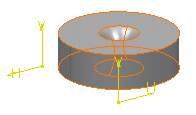
The groove is created. Groove.XXX node is added to the tree.

- Double-click the groove to edit it.
-
Enter the limiting angle values.
The preview of the groove appears about the axis.
-
Click
OK.
The material surrounding the profile is removed.
