Add Insulation on a Route
You can add insulation on a route.
-
From the Fluid Design section of the action bar,
select Insulation Mode
 as process
mode.
-
From the Selection Options dialog box, select Part
Selection
 .
For more information about the different selection options, see Selection Options and Process Modes.
 - Select the rigid or flexible route to add insulation.
-
On the context toolbar, click Insulate Route
 .
.
-
From the Insulate Route panel, select the options of your
choice:
Option Description Insulation Mode  In-spec: Filters the insulation reference according to
insulation specifications defined in the Data Information panel. The
Available Parts dialog box is displayed to let you select
the insulation reference of your choice.
 Reference Part: Copies insulation from an existing one.
Insulation Length  Whole Route: Applies insulation on the whole route.
 Partial Route: Applies insulation on a part of the route.
For partial insulation, you need to select two node points. Insulation is created
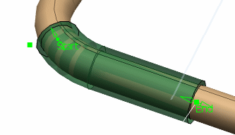
between these two node points.The insulation is added to the route and start and end insulation points appear at the insulation extremities.
- Optional:
Drag the green arrows to reduce or extend the insulation between
the two selected nodes.
You can also double-click the start or the end point and enter a value in the Parameter Definition dialog box.Note:
- You can add multiple insulations to the rigid or flexible route. The image below illustrates two insulations added on one
pipe/tube.

- If you want to place insulation from a particular specification, select the appropriate context in the Data Information panel.
- You can add multiple insulations to the rigid or flexible route. The image below illustrates two insulations added on one
pipe/tube.
-
Click
 to validate the
insulation creation.