 -
Create a logical reference. For this scenario,
name it Annotation_Break_Logical_Reference.
-
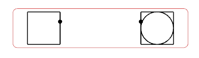
Create and edit the symbol representation of the logical reference. See Creating a Symbol Representation.
Notes:
The symbol representation must at least include:
-
From the Symbol Edition section of the action bar,
click Exit App
 to exit
Symbol Design. to exit
Symbol Design.
-
Display the diagram view in which the two components to be connected are placed.
-
From the Edition section of the action bar,
click Create Pipe.
The Create Pipe dialog box appears. The name of the pipe
previously created appears in the Pipe Reference box.
- In the Piping Line ID area, select New line ID: a new line ID is created.
-
Define the Pipe Specification attribute of the
line ID.
- In the Pipe specification box, enter Spec 1.
- Route your pipe.
- Right-click the logical reference and select Insert Existing Logical Component.
- Select Annotation_Break_Logical_Reference in the tree.
The annotation break symbol appears and follows your pointer. - Place the annotation break symbol over the pipe and click.
The annotation break symbol is placed and a context toolbar appears to let you flip or rotate.  - Click anywhere in the diagram view to validate the symbol position.
The logical pipe is split in two pipes and the text template is resolved. The annotation break displays the specification of the left pipe. 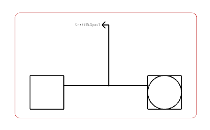 Notes:
- By default, the two created pipes have the same specification as the line ID. If you change the specification of the left pipe, the text template is automatically resolved.
- To display the specification of the right or upper pipe, place it in the view, and then flip or
rotate the symbol representation of the annotation break. Click validate.
|
