-
From the Control section of the action bar, click Geometric Tolerances Checker
 . .
-
Select a segmented mesh.
- The mesh on which you verify the GD&T elements must be properly aligned with the
corresponding exact CAD data (for example by best fit).
-
Geometric Tolerances Checker analyses a segmented mesh, each cell corresponding to a geometry potentially pointed by a GD&T.
- You can select a segmented mesh, or let Geometric Tolerances Checker do the segmentation.
-
Select the GD&T to check.
Pick a GD&T or the CAD surfaces related to the GD&T
- You can select the GD&T by a direct pick.
- You can pick the CAD surfaces related to the GD&T. In this case, tolerances are deduced from the surfaces.
The dialog box is updated: - The name (single selection) or the number (multiselection) of the GD&T selected is listed
under Tolerances.
- The name of the GD&T selected and their requested tolerances are listed under Analysis.
- Optional: Select the Radius check box.
The points found inside a circular pipe with this radius and centered on the CAD boundaries are ignored for the computation. -
Click Apply.
Each found tolerance is evaluated and the measured value is displayed with an OK or KO status.
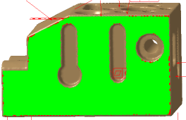
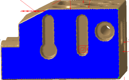
- Select a row in the dialog box.
The defect is highlighted in the work area, with a color
map:
- The areas in green meet the tolerance.
- The areas in red are above the tolerance.
- The areas in blue are below the tolerance.
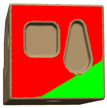
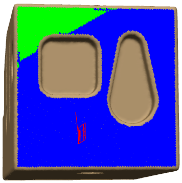
- Some tolerances are evaluated from a reference named
datum. Depending on the type of the tolerance, this reference may
slightly move around its default position. This is the "clearance"
of the reference.
Use the slider in the dialog box to move the reference from one
extremity to the other
The distribution of colors changes in the defect
map.
- Click Cancel to exit the dialog box without saving the inspection results or click OK to exit the dialog box and save the check result, as a GD&T Check.x feature.
-
Insert this
GD&T Check into a Deviation Report.
- In the Deviation tab, click Add in More Elements to Export and select the GD&T Check.x feature you want to insert.
You can add several GD&T Check.x features.
Note:
The exported report contains a dedicated section.
- Create a snapshot of the deviation check result.
In the Insert Images tab, add the snapshot.
Note:
The exported report contains the snapshot in the User Defined Results section.
|