-
From the ECAD Collaboration section of the action bar, click Compare & Update
 . .
The Compare and Update dialog box
is displayed with the following options: In the Board Update Options area: - Check on Board
- No check on Board
-
Select:
- Check on Board, if you want to check the differences between your rigid flexible board and the new IDF file. By default, all this option and the first four check-boxes are selected (Check Holes, Constraint Areas, Annotations, Pocket). If you know precisely which element is new, you can uncheck boxes. Checking elements on rigid flexible board is obviously more time consuming than no check at all.
- No check on Board: If you select this option, the comparison of
differences between the rigid flexible board assembly and the IDF file will not
take place. Therefore the import without check will be more
rapid (Compare & Update process being time consuming).
- In the Selected files area of the dialog box, select an IDF file.
You can select a file on disk or in the database. You can load objects in session by
running the Content
Chooser. See Using the Content Chooser. -
Click OK to launch the Update process. The Comparison Report window is displayed.
There are six tabs displaying the differences found in the: - Board Assembly: boards, holes and pockets are concerned
- Component: components
- Area: constraints
-
Select a line in the report and right-click the terms To Validate in the Status column: you can either Validate selected modification(s) or Reject selected modification(s):
If you select Reframe on selected Modifications, you focus in on the selected object in the work area and the dialog box remains opened. In the Modification detail space, explanations are given about the modifications detected.
You can add a comment in the User comment column. It will be visible in the Textual Report or in the Attached Report (see step 7 & 8). -
Click:
 if you need to select or unselect all the objects in the list. if you need to select or unselect all the objects in the list.-
 to select or unselect all the new objects in the list. to select or unselect all the new objects in the list. -
 to select or unselect all the modified objects in the list. to select or unselect all the modified objects in the list. -
 to select or unselect all the deleted objects in the list. to select or unselect all the deleted objects in the list.
-
Check Generate Textual Report to obtain a list of the changes and validation / refusal.
To have access to this report, click Advanced Search in the Menu. The Report Path directory can be set in the Board Assembly tab of Circuit Board Design options in .
- Check Attach the Report under the Board Assembly to save the report under the board assembly.
You can see the Report name in the Propagate dialog box when you save the board assembly. To retrieve the report, select Explore > Document > Show Attached Documents. Then you can see the report in the board assembly tree and click Open.
- Select to save these modified boards, components and areas in the database.
- Click OK or Cancel to validate your approval or refusal of IDF modifications.
If you click OK, the selected objects (Area in our example) are inserted in the board and they are highlighted in 3D area and in the tree. 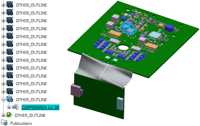
|
 > Preferences .
 > Save > Save with Options to save these modified boards, components and areas in the database.