You can define a sketch plane on the fly, by hovering over and selecting a
planar/curved surface, an edge, a plane or a point, before switching to the Sketcherapp. If the plane is not suitable, you can position it with
commands available in a context toolbar.
You can solve rebar self-intersection in the Rebar Creation dialog box
and obtain a 3D valid profile for the bar. You can choose the distance used for the bar
spacing at the crossing location and the position of the final wire with respect to the Sketch
support.
From the Reinforcement section of the action bar, click Rebar Creation.
Click Wire selection to define a rebar layer based on wires.
To define a plane, click Smart Sketch Plane.
Hover over a planar or curved surface, an edge, a plane or a point.
Depending on your selection, the result is as follows:
Selection
Result
A planar surface
The plane of the surface is proposed and the origin of the plane is the
mouse cursor position.
A curved surface
A tangent plane to the curved surface is proposed and the origin of the
plane is the mouse cursor position. The plane normal vector is the normal vector
of the face at the cursor position.
An edge
A normal plane to the edge is proposed and the origin of the plane is the
cursor position.
A plane
An offset plane to the selected plane is proposed and the origin of the
created plane is the origin of the selected plane.
A point
If the point is a point on curve or a tangent point (with specifications),
the origin of the plane is the point itself. The plane is created normal to
the support of the point.
If the point is a 3D point (with coordinates), the plane of the last flown
over surface or edge is proposed, and the origin of the plane is the point
itself.
Note:
At this stage, press Escape to go back to the
Rebar Creation panel and click Cancel,
or click the geometry to validate the plane position.
You can refine this position by
using manipulators and context toolbar commands to edit it more accurately in the 3D area.
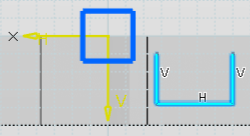
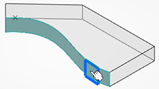
Pick an element according to your needs.
In the example below, when you select an edge, a dimension is displayed.
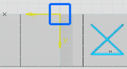
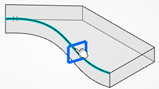
Some geometric features (point, plane) are aggregated under the current Rebar layer
feature, visible in the Geometrical Set in the tree, under the Wire selection node. And a manipulator is proposed
in the 3D area:
Notes:
Once you have initialized your design, you can refine its positioning by
editing/isolating some elements of the sketch plane.
Once the Sketch plane is validated by the Smart Sketch Plane
command, you can no longer re-enter the command. If you need to modify the plane, use
the context toolbar options (see next step).
Click the dimension and change its value in the Parameter
Definition panel.
Optional:
Modify the plane position by selecting the context toolbar options of your
choice:
Option
Description
Sketch
Launch the Sketcherapp with the plane as support.
Point
Edits the point on curve or the point on surface feature.
When editing the
point, you can choose either an Euclidian distance (with the m unit, a straight line
distance between two points) or a Geodesic distance (with the G unit, the minimum
length between two points inside/along a curved surface).
Plane
Edits the Normal to curve plane or the Offset plane.
Robot Axis
Moves the plane using the Robot which is automatically dropped onto a plane or
an axis system. It provides handles for translation rotation and alignment. And you
can modify the plane direction and orientation according to the robot axis.
Isolate
Isolates the point and the plane for free modifications.
Exit
Exits the command and go back to the Rebar Creation
command.
In the Sketcherapp, the created geometry is always included in a plane.
In Rebar design, you can first draw a bar profile in 2D even with self-intersections
and, some parts of the wire are moved automatically to generate a 3D profile.
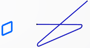
Examples of wire sketching (with or without intersection):
The above edition commands are still available in a context toolbar at the top of the
Concrete Structures 3D Designapp.
After changing dimensions, you can visualize the rebar wire based on the
sketch plane:
A wire with self-intersection (see next step):
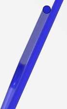
Click Exit to switch back into the Concrete Structures 3D Designapp and click Apply in the
Rebar Creation dialog box. You obtain a 3D profile of the
bar:
A bar profile in 2D with self-intersection
To solve rebar intersection, use the Solve self-intersections
option in the Rebar Creation dialog box. This option is selected by
default and can manage multi self-intersections on the same bar.
Before the solving operation, you can see the contact location:
Note:
If you deselect the Solve self-intersections option, the
sketch is not modified and remains as created.
To specify the offset distance between bars, use the following Wire
Parameters:
Bar axis offset: the distance used for the bar
spacing at crossing location.
Bar spacing location equal to the bar diameter
By default, this value is the bar radius multiplied by 2.
Bar spacing location superior to the bar diameter
After edition of the Bar axis offset, you
obtain:
Side: the position of the final wire with respect
to the Sketch support:
Front Side:
On the front side, the first edge of the sketch is fixed and the rest of
the bar moves to solve the self-intersection.
Rear Side:
On the rear side, the last edge of the sketch is fixed and the rest of the
bar moves to solve the self-intersection.
 .
.
 to define a rebar layer based on wires.
 .
.


 Notes: