The point representation of the tool shape is useful for
situations where the action zone of the tool is very small compared to the mesh
size and can be idealized as a point; for example, when the laser beam radius
is very small compared to the element size.
Figure 1
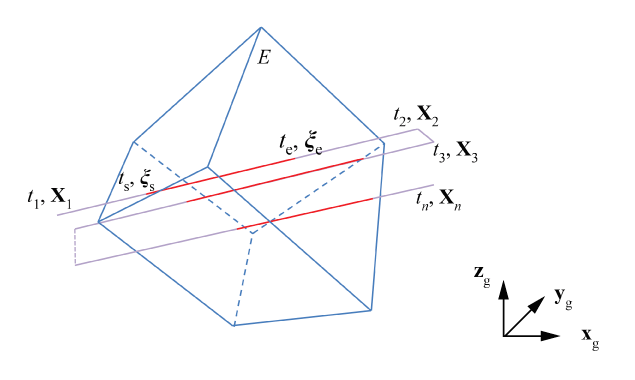
depicts intersections of a point toolpath with a finite element,
.
The toolpath is defined by the path connecting points
at times .
It is assumed that the tool travels at a constant velocity over a segment
connecting two successive points in the path. The first field defined in the
event series represents a state of the tool, such as the laser power. The field
defined for a point
remains constant over the segment connecting
and .
All path segments where the tool is in the "on" state are required to be
perpendicular to the global -direction.
For a given element, the toolpath-mesh intersection module computes the number
of intersections of the toolpath, the coordinates of the start and end points
(s
and e,
respectively, expressed in the element reference coordinate system), and the
start and end times (ts and
te, respectively) for each intersection.
Figure 1. Point toolpath-mesh intersection.