Problem description
A one-dimensional fluid column in a rigid pipe with a constant cross-sectional area is modeled with AC2D4R elements. At the top of the column the fluid is coupled to an idealized floating structure, represented by two vertically oriented masses ( and ) connected by a spring with stiffness K. Figure 1 shows a schematic of the model. The fluid-solid system is excited by a plane, upward-propagating, step-exponential wave, applied at the bottom of the fluid column. A plane wave absorbing boundary is also applied at the bottom of the column, which is exact for one-dimensional acoustic waves.
To simulate the mass , one point mass element is attached to a node vertically aligned with each of the uppermost two nodes of the fluid column. In the mass-spring models two other point masses are attached to nodes 5.08 m above the uppermost fluid nodes to simulate the mass , and the corresponding point mass nodes are linked with spring elements. At the top of the fluid column, the fluid response is coupled to that of the structure using a tie constraint. At the bottom of the fluid column, a plane wave, nonreflecting boundary condition is applied. The step-exponential wave is applied on the bottom surface of the fluid column using incident wave loading, which refers to an amplitude curve that contains the discretized pressure-time history of the wave at the standoff point (the bottom of the fluid column). The point masses are constrained in all directions except the vertical (degree of freedom 2). The nondefault total wave formulation is used to capture the effects of cavitation. The cavitation pressure limit for the acoustic medium is set to zero, thus initiating cavitation whenever the absolute pressure (sum of the incident, scattered, and static pressure) becomes negative. The initial acoustic static pressure in the fluid is specified.
Single-mass case
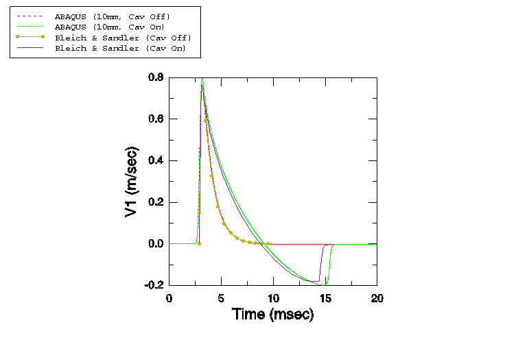
In the first part of this example is set to zero, duplicating the model problem published in Bleich and Sandler (1970).
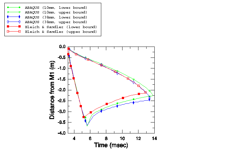
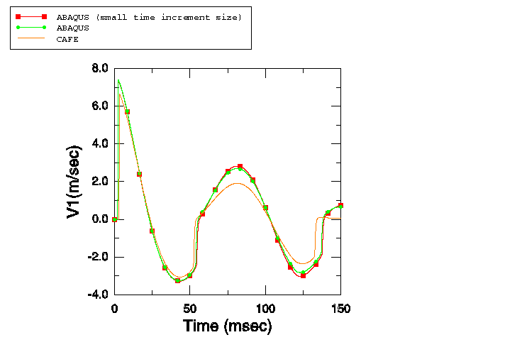
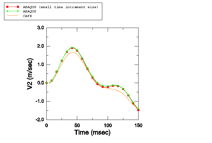
The fluid column depth is 3.81 m. A single stack of AC2D4R elements is used to mesh this column, with all elements 38.1 mm in width and 1.0 m in out-of-plane thickness. The draft of the floating mass is 0.145 m. Atmospheric pressure is 0.101 MPa. The fluid density is 989.0 kg/m3, the acoustic velocity is 1451.0 m/s, and the acceleration of gravity is 9.81 m/s2. The fluid properties yield a bulk modulus of 2.082242 GPa, which is the value that is specified along with the fluid density. The initial conditions are specified in such a manner that the pressure at the free surface is the sum of the atmospheric pressure and the pressure caused by the floating mass. Hence, the initial pressure is applied as a linear variation from p = = 0.101 MPa at a height of 0.145 m (to include the effect of the floating mass) to p = = 0.13937177 MPa at the bottom of the fluid column. The maximum pressure in the step-exponential wave is 0.7106 MPa, and the decay time is 0.9958 ms. This model is studied using a coarse mesh of 100 elements, each 38.1 mm in height, and a fine mesh of 381 elements, each 10 mm in height.
In addition, two time increment sizing methods are compared: that used by Sprague and Geers, and the time increment size automatically computed by Abaqus/Explicit. Sprague and Geers have used a fixed time increment = /2, where is the Courant-Friedrichs-Lewy time increment limit, computed as = /c, where is the element height. Thus, for the 38.1 mm case this requirement yields a time increment of 13.12887 s, while for the 10 mm case it yields a time increment of 3.445889 s.
Multiple-mass case
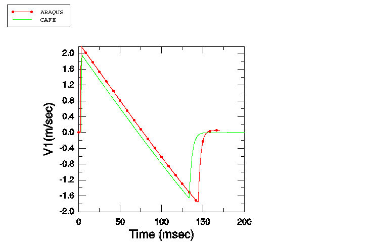
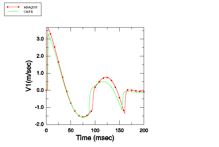
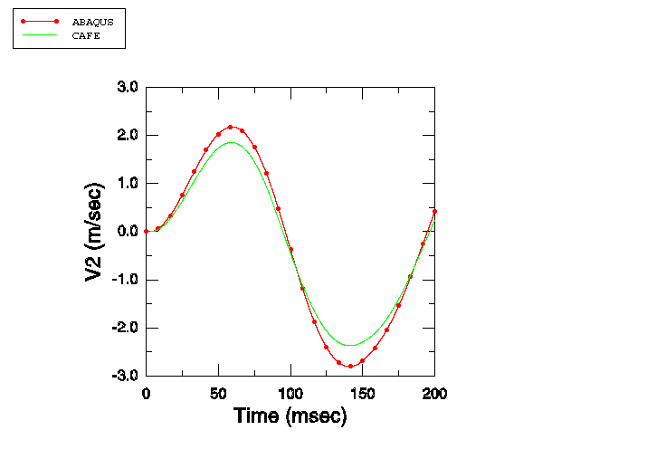
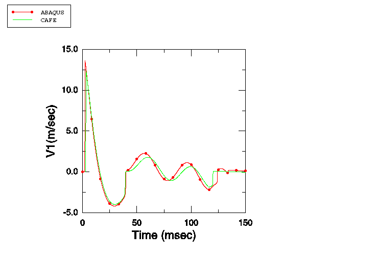
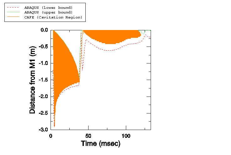
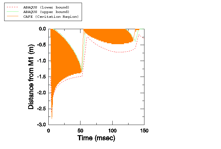
In the second part of this example the ratio of / is varied to study the cases of Sprague and Geers (2001). Four cases are examined: / = 0, / = 1, / = 5, and / = 25. The results obtained are compared with those obtained by Sprague and Geers (2001) with Cavitating Acoustic Finite Element (CAFE) models.
The fluid column depth is 3.0 m. A single stack of AC2D4R elements is used to mesh this column, with all elements 2.5 mm in height, 10 mm in width, and 1.0 m in out-of-plane thickness. Atmospheric pressure is 0.101 MPa. The fluid density is 1025.0 kg/m3, the speed of sound is 1500.0 m/s, and the acceleration of gravity is 9.81 m/s2. The draft is 5.08 m for all the models, so that the mass of displaced fluid is equal to the displaced volume times the fluid mass density, or 52.07 kg. In the case where / = 0, this mass is entirely assigned to . In the second case / = 1. To keep the draft constant at 5.08 m, the total mass of and must equal 52.07 kg. Dividing it equally between and yields = = 26.035 kg. For the case / = 5, is assigned a mass of 8.678333 kg, while is assigned a mass of 43.391667 kg. For the fourth case / = 25; hence, is 2.0026923 kg, while is 50.067308 kg.
The spring constants defined in the reference paper are such that the fixed-base natural frequency of mass is 5 Hz in all the cases: K = (5 × 2). Thus, for the case / = 1, K = 12847.758 kg/s2; for / = 5, K = 21412.929 kg/s2; and for / = 25, K = 24707.226 kg/s2.
The initial conditions are specified as in the single-mass case, with atmospheric pressure of 0.101 MPa applied 5.08 m above the free surface and 0.212412 MPa applied at a depth of 6 m. The maximum pressure in the step-exponential wave is 16.15 MPa, and the decay time is 0.423 ms.
For all the mass ratio cases, analyses are performed using a fixed time increment size = /2, which is 0.8333 s. For the case where / = 5, the effect of using a smaller time increment size ( = /20 = 0.08333 s) while holding all other parameters constant is also analyzed.
Submodeling
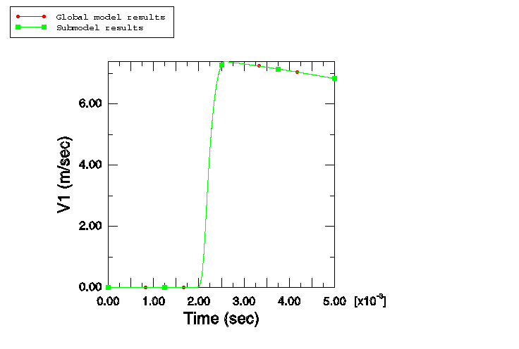
These types of analyses can also be performed using the acoustic-to-structure submodeling technique; this study includes a case where the results obtained by performing an analysis with the submodeling technique are compared with those obtained using the default global analysis technique. The submodeling technique illustrated here is useful in situations where the structural response is of primary interest and the presence of the fluid is required mainly for the application of the underwater explosive load onto the structure. In such situations it is possible to perform a single global analysis with a fluid mesh, followed by multiple submodel analyses without the fluid mesh wherein the structural parameters are varied and the effects analyzed. Due to the absence of the fluid mesh in the submodel analyses, computational effort may be significantly reduced. In this study the submodeling technique is illustrated for the case / = 5 and is run for a step time of 5 ms. First, a global analysis is performed and the structural displacements (U) and acoustic pressures (POR) at the top of the fluid stack are written to the results file. Following the completion of the global analysis, the submodel analysis is performed, wherein the model consists of the structure only and no fluid mesh is present. This structural submodel is driven by the acoustic pressure results extracted from the global analysis.
Modeling cavitation using displacement-based elements
In certain underwater explosion situations—for example, when an underwater explosion occurs near a submarine—the explosion can cause large structural displacements of the submarine hull. In cases where the structural displacements are extremely large, as occurs during plastic failure of the hull, the fluid migrates to fill the displaced volume. This large motion of the fluid is best modeled with displacement-based continuum elements that can be adaptively meshed to avoid extreme mesh distortions in Abaqus/Explicit. To demonstrate this modeling technique, the cavitation of the one-dimensional fluid column is modeled using a single stack of CPE4R elements instead of AC2D4R elements. The geometry and material properties used are identical to the multiple-mass case. The effect of the hydrostatic pressure is simulated using gravity loading on the fluid column, with an additional distributed pressure load defined on the top of the fluid column to account for the effect of the atmospheric pressure and the draft of the floating masses. To establish an initial equilibrated state, geostatic initial stresses are specified. An equation-of-state material of the linear form is used to model the fluid, and a tensile failure model is used to simulate cavitation in the fluid medium. The material parameters are chosen to closely match the acoustic medium properties used for the acoustic element simulation. At the bottom of the fluid column, nonreflecting boundary conditions are applied by defining a displacement-based infinite element of type CINPE4. Adaptive meshing is used to adaptively remesh the fluid domain to prevent excessive mesh distortions. The loading is identical to that used for the multiple-mass case.


