Acoustic scattering from an elastic spherical shell

This example calculates the acoustic near field scattered from an elastic spherical shell when impinged by a plane wave. The example illustrates the use of simple absorbing boundary conditions, acoustic continuum elements, acoustic infinite elements, tie constraints, and incident wave interactions. The results are compared with a classical solution.

This page discusses:

ProductsAbaqus/Standard

Problem description

A thin spherical shell of radius r0 = 0.1 m and thickness h = 0.001 m in an unbounded acoustic medium is subjected to an incident plane wave. The analytical solution for the acoustic scattered pressure is of the form

pscat=pelastic+prigid,

where

prigid(r,θ)=-Pincidentn=0(2n+1)inPn(cosθ)jn(kr0)hn(kr0)hn(kr),
pelastic(r,θ)=Pincidentρfc0k2r02n=0(2n+1)inPn(cosθ)hn(kr)hn(kr0)1Zn+zn.

The elastic pressure term uses the in-vacuo modal impedance of the shell,

Zn=ihρfc0r0Ω[Ω2-Ωn,12][Ω2-Ωn,22]Ω2-(1+β2)(ν+n(n+1)-1),

and the specific acoustic modal impedance,

zn=iρfc0hn(kr0)hn(kr0).

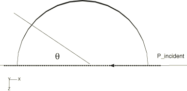
Definitions of the terms in the expressions above are found in Table 1. The orientation of the incident wave with respect to the sphere is shown in Figure 1; the incident field is defined as having zero phase at the origin, which lies at the center of the sphere. The analytical solution is derived in Junger and Feit, but its complex conjugate is used for comparison to conform to the Abaqus sign convention for time-harmonic problems.

The finite element mesh uses AC3D20 elements to model the fluid, with an outer radius of r1 = 0.25 m and a circumferential angle of 10°. Since the problem is axisymmetric, this is sufficient to resolve the field. The shell is meshed with S8R elements, and this mesh is coupled to the acoustic mesh using a tie constraint. Planar incident wave loads of unit reference magnitude are applied to the inner acoustic and outer shell surfaces, with the standoff point defined at the center of the sphere and the source point defined at a point along the positive x-axis. Specifying the load in this way means that Abaqus will apply loads on the surface corresponding to an incident pressure field having a value of 1 + 0 × i at the standoff point. Two Abaqus models are created: in one, a spherical nonreflecting condition is imposed on the outer surface; in the other, acoustic infinite elements are created and coupled to the acoustic finite elements using a tie constraint. The material properties used in this problem are shown in Table 2. The analysis is run using the direct-solution steady-state dynamic procedure in the range from 1500 to 5000 Hertz.
Results and discussion

The finite element results for the scattered pressure in the near field, at a frequency of 1500 Hz, are shown in Figure 2, where they are compared with the analytical values. The figure depicts the analytic near field on the upper annulus and the finite element solution on the lower one. The real parts of the solutions show very good agreement.

References

  1. Bayliss A.MGunzberger, and ETurkel, Boundary Conditions for the Numerical Solution of Elliptic Equations in Exterior Regions,” SIAM Journal of Applied Mathematics, vol. 42, no. 2, pp. 430451, 1982.
  2. Junger M. and DFeit, Sound, Structures, and Their Interaction, The MIT Press, 1972.

Tables

Table 1. Variable definitions.
Variable Definition
pscatScattered acoustic pressure
pelasticElastic contribution to scattered pressure
prigidRigid contribution to scattered pressure
PincidentIncident plane wave coefficient
PnLegendre polynomial
jn(kr0)Spherical Bessel functions of the first kind
hn(kr0)Spherical Hankel functions of the first kind
k=2πf/cfAcoustic wave number
cf=Kf/ρfSpeed of sound
fFrequency
Ω2πfr0cp
Ωn,1nth resonant frequency of shell in-vacuo, first branch
Ωn,2nth resonant frequency of shell in-vacuo, second branch
β2Thin-shell section parameter, h212r02
cpPlate wave speed, E(1-ν2)ρs
Table 2. Material properties.
Parameter Value
Kf2.0736 GPa
ρf1000 kg/m3
cf1440 m/s
E180.3 GPa
ν0.3
ρs7670 kg/m3

Figures

Figure 1. Orientation of the incident wave with respect to the sphere.

Figure 2. Pressure (POR) at 1500 Hz—real part.