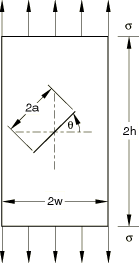
The calculated stress intensity factors are compared with the solutions taken from Page 909 of the Stress Intensity Factors Handbook, edited by Y. Murakami.
Table 1. Nondimensional stress intensity factor results for isotropic elasticity. Contour 1 is omitted from the calculation.
| | | |
| Reference solution |
0.5719 |
0.5290 |
| Abaqus |
0.5540 |
0.5289 |
Based on the stress intensity factors and , Abaqus can automatically predict the crack propagation direction, which is an angle measured with respect to the crack plane. For example, −52.41° if the maximum tangential stress criterion is used, −55.76° if the maximum energy release rate criterion is used, and −56.12° if the 0 criterion is used.
Abaqus also outputs the J-integral value estimated by the stress intensity factors, = 3.4517 × 10⁻³, which agrees very well with the J-integral value estimated directly, = 3.4515 × 10⁻³.
In addition, the stress intensity factors and the J-integral are evaluated for the same plate using four different anisotropic, linear elastic materials: orthotropic elasticity specified by the engineering constants (denoted by ENGC), orthotropic elasticity specified by the stiffness parameters (ORTH), fully anisotropic elasticity (ANIS), and lamina elasticity (LAMI). The model with lamina elasticity is meshed using plane stress CPS8 elements. The results are summarized in Table 2. Though no published solutions are available for comparison, the J-integrals from the stress intensity factors are in very good agreement with the J-integrals evaluated directly.
Table 2. Nondimensional , , and values for a slant crack. Contour 1 is omitted from the average value calculation.| Elasticity | J-integral value estimated by the stress intensity factors | J-integral value estimated directly |
|---|
| | × 103 | × 103 |
|---|
| ENGC |
0.5717 |
0.5299 |
2.8740 |
2.8750 |
| ORTH |
0.599 |
0.5429 |
2.1931 |
2.1930 |
| ANIS |
0.5388 |
0.5260 |
4.3790 |
4.3798 |
| LAMI |
0.5391 |
0.5223 |
4.7639 |
4.7637 |