Fluid filled rubber bladders

This example illustrates the transfer of fluid between two rubber bladders subjected to external axial compression. There is a fluid exchange between the two bladders so that fluid can move between them. The amount of mass transfer depends on the pressure differentials between the bladders.

This page discusses:

ProductsAbaqus/Explicit

Problem description

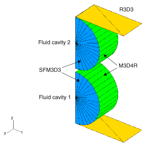
The bladders are modeled as short cylinders (with M3D4R elements) or spheres (with SAX1 elements) with a radius of 1.0 m and a wall thickness of 0.05 m. Ogden hyperelasticity (N=3) with material coefficients calibrated by Abaqus from experimental stress-strain data is used for the rubber constitutive equation. The fluid in the bladders is modeled as fluid cavities. The fluid cavity's reference node must lie on the symmetry plane or the symmetry axis, respectively. The normals to the element-based surface must point into the fluid cavity to obtain the correct cavity volume. The ambient pressure is assumed to be 50.0 kPa, and the fluid is prepressurized to a gauge (additional) pressure of 8.2736 kPa. Static equilibrium requires that the rubber bladders also be subjected to a uniform initial stress of 165.972 kPa along the circumferential direction in the M3D4R elements and a uniform in-plane initial stress of 82.736 kPa in the spheres.

The transfer of fluid is modeled by using a fluid exchange definition and specifying the bulk viscosity for the fluid exchange property. The viscous coefficient, CV, and the hydrodynamic resistance coefficient, CH, are chosen to be 10000.0 and 100.0, respectively. These resistance coefficients determine the mass flow rate at any time instant as a function of the pressure differential between the two bladders.
Results and discussion

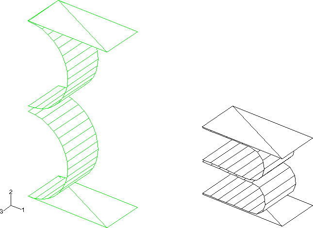
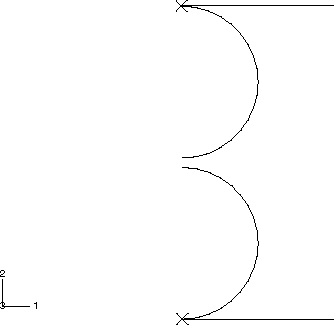
The bladder systems are impacted by a rigid body at a constant downward velocity of 4.0 m/s. The total time of the event is 0.64 sec. Figure 1 gives the initial configuration of the three-dimensional model. Figure 2 shows the final deformed shape of the cylindrical rubber bladders. Figure 3 gives the initial configuration of the axisymmetric model. Figure 4 shows the final deformed shape of the spherical rubber bladders. The fluid pressures inside the two containers are plotted in Figure 5 and Figure 6. The pressures in the two bladders are almost the same, owing to the fluid link, which drives the flow of fluid if there is any pressure differential between the two bladders. The pressure in the cylinders rises more than the pressure in the spheres as the relative volume change in the spheres is less than in the cylinders. The pressure in the cylinders and the spheres shows oscillations that are caused by the stiffness associated with flattening of the spheres.
Figures

Figure 1. Initial (undeformed) configuration for the 3D case.

Figure 2. Undeformed rubber bladders on left and deformed rubber bladders on right. The bladders are modeled with M3D4R elements.

Figure 3. Initial (undeformed) configuration for the axisymmetric case.

Figure 4. Undeformed rubber bladders on left and deformed rubber bladders on right. The bladders are modeled with SAX1 elements.

Figure 5. Fluid pressures in the two cylindrical rubber bladders.

Figure 6. Fluid pressures in the two spherical rubber bladders.