Uniaxial tests on jointed material

This example illustrates the fundamental material behavior obtained with the jointed material model in Abaqus. We construct a failure envelope for a material containing two sets of joints and subjected to uniaxial stress conditions. A complete description of the model is given in Constitutive model for jointed materials.

This page discusses:

ProductsAbaqus/Standard

Problem description

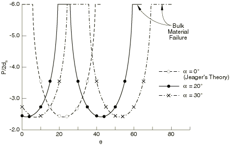
We consider a sample of material subjected to uniaxial compression/tension. The material has two sets of planes of weakness having an included angle of 2α. We seek to construct the failure envelope of the material as the orientation (θ in Figure 1) of the planes of weakness is varied.

In the Abaqus model the failure surface for sliding on the joint systems is defined as

fa=τa-patanβa-da=0,

where pa is the pressure stress across the joint, τa is the shear stress magnitude in the joint, βa is the friction angle of the joint, and da is its cohesion. For this problem we assume that for both joints da=1000 (the units are not important), βa= 45°, and that plastic flow in the joints is associated.

The behavior of the bulk material is based on the Drucker-Prager failure criterion

q-ptanβb-db=0,

where q=def32SS is the Mises equivalent deviatoric stress (here S is the deviatoric stress S=defσ+pI), p=def-13I:σ is the equivalent pressure stress, βb is the friction angle of the bulk material, and db is the cohesion of the bulk material. For this problem we assume that db= 8000, βb= 45°, and that plastic flow of the bulk material is associated.

When all the joints are closed, the material is assumed to be isotropic and linear elastic with a Young's modulus of 3 × 10⁵ and a Poisson's ratio of 0.3. When a joint opens, the material is assumed to have no elastic stiffness with respect to direct strain across the joint system or with respect to shearing associated with this direction. Open joints, thus, create anisotropic elastic response.

Each test performed in this example is carried out using a cube (one C3D8 element) of unit dimensions. Displacements are prescribed at the nodes of the cube to simulate homogeneous deformation and stress conditions.

Results and discussion

Figure 2 shows the variation of the compressive failure stress P/2da with θ, the angle which the bisector of the joints forms with the direction of the load. Compression failure envelopes are developed for α= 0°, 20°, 30°. It is clear that for certain ranges of orientation of the joints with respect to the loading direction, failure along the planes of weakness becomes increasingly improbable and failure of the bulk material takes place first. It may be noted that the case when α=0° corresponds to the theory of a single plane of weakness proposed by Jeager (1960).

When the load is applied in tension, the material cannot carry any stress since the joints open readily.

Input files

jointedmat_comp_alpha20thete0.inp

Compression test with α= 20 and θ= 0.

jointedmat_comp_alpha20thete20.inp

Compression test with α= 20 and θ= 20.

jointedmat_tens_alpha0theta10.inp

Tension test with α= 0 and θ= 10.

jointedmat_tens_alpha20theta20.inp

Tension test with α= 20 and θ= 20.

jointedmat_comp_pert.inp

A version of jointedmat_comp_alpha20thete0.inp including linear perturbation steps.

jointedmat_tens_pert.inp

A version of jointedmat_tens_alpha0theta10.inp including linear perturbation steps.

The remaining cases analyzed in this example problem can be generated by changing the orientation of the joints.

References

  1. Jeager J. C.Shear Failure of Anisotropic Rocks,” Geological Magazine, vol. 97, pp. 6572, 1960.

Figures

Figure 1. Problem geometry.

Figure 2. Uniaxial compression failure envelopes.