A penny-shaped crack under concentrated forces

The example illustrates the analysis of a penny-shaped crack in an infinite body, subjected to concentrated forces.

The analytical solutions for the stress intensity factors can be found on pages 672–673 of the Stress Intensity Factors Handbook edited by Y. Murakami.

This page discusses:

ProductsAbaqus/Standard

Problem description


The geometry analyzed is a penny-shaped crack in an infinite body, subjected to concentrated forces P and R, as shown in the above figure. The size of the body is chosen big enough relative to the crack radius, a, such that an infinite body containing a small penny crack can be modeled. The ratio of lengths b/a= 0.66. The material is linear elastic, with Young's modulus = 200 GPa and Poisson's ratio = 0.3. Two remote points on the z-axis in the body are fixed to prevent rigid body motion. The loading is P=R= 400 MN.

Results and discussion

Due to symmetry only the results from ϕ= 0° to ϕ= 180° are presented, although the calculations are carried out for a full solid body. The calculated stress intensity factors are compared with the analytical ones in Figure 1.

Abaqus outputs the J-integral values estimated by the stress intensity factors when the latter are requested. They are compared with the J-integral values calculated directly and also compared with the analytical J-integral solutions in Figure 2.

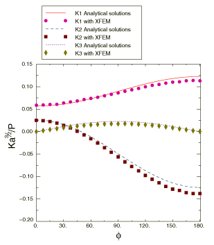
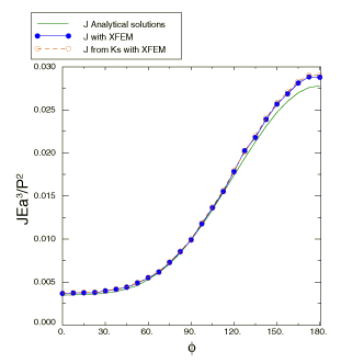
The stress intensity factors and the J-integral values are also evaluated using the extended finite element method (XFEM). The values are compared with the analytical solutions in Figure 3 and Figure 4.

Figures

Figure 1. Variation of the stress intensity factors with ϕ.

Figure 2. Variation of the J-integral with ϕ.

Figure 3. Variation of the stress intensity factors with ϕ obtained using the extended finite element method.

Figure 4. Variation of the J-integral with ϕ obtained using the extended finite element method.