The pinched sphere problem

This example verifies the use of the axisymmetric shell elements to analyze a pinched sphere.

Most of the response is localized, so the case represents a more severe test than, for example, a sphere with internal pressure. Koiter (1963) has provided an analytical solution, which has been used as a standard test for several axisymmetric shell finite elements (see Ashwell and Gallagher, 1976).

This page discusses:

ProductsAbaqus/StandardAbaqus/Explicit

Problem description

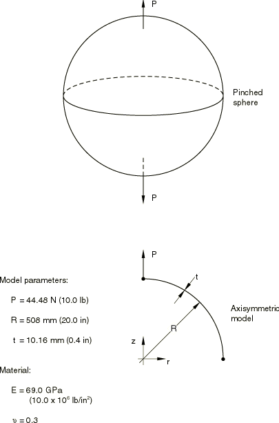
The physical problem consists of a hollow sphere with opposing point loads acting along a diameter of the sphere (see Figure 1). Taking advantage of symmetry in the model, only one-half of the sphere is modeled. The meshes used for this example are uniform, although in an actual problem that exhibits such localized response the mesh should be refined to concentrate the elements in the region where the strain gradients are most severe. Four axisymmetric meshes are used for the Abaqus/Standard analysis. For the linear 2-node element, SAX1, the meshes have 10 and 20 elements. For the quadratic 3-node element, SAX2, the meshes have 5 and 10 elements. Two three-dimensional models made up of a single strip of shell or continuum shell elements that subtend an arc of 6° in the circumferential direction are also tested in Abaqus/Standard. Two SAX1 meshes are used for the Abaqus/Explicit analysis, one with 10 elements and the other with 20 elements.

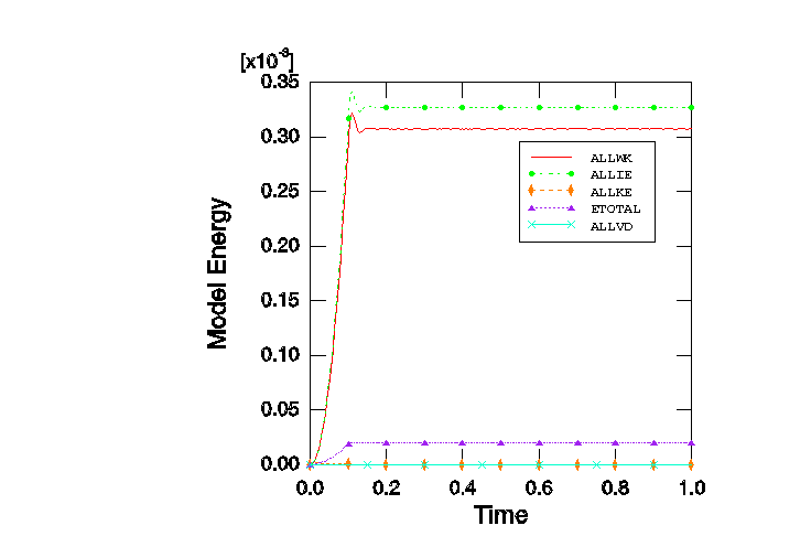
In the Abaqus/Explicit analysis the quasi-static pinching load is applied as a ramp function during the initial 10% of the time period for the step and is then held constant for the remainder of the step. Additionally, viscous pressure loading is applied to the structure to damp out dynamic effects. The time period for the step and the viscous pressure are chosen to obtain an optimal static solution.
Results and discussion

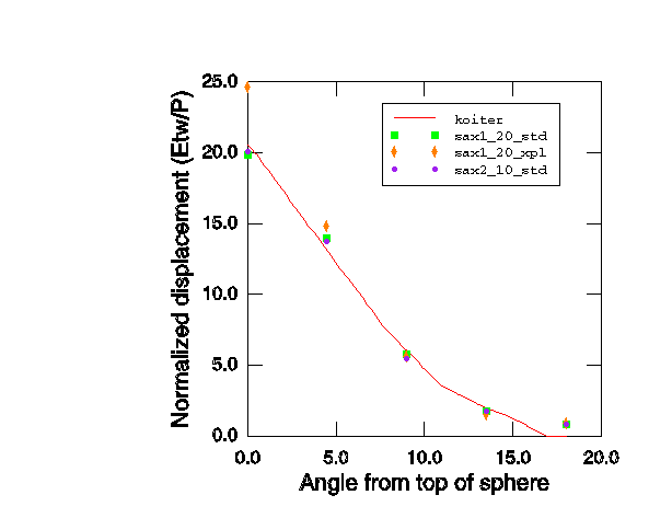
Figure 2 shows the numerical predictions of radial displacement compared with Koiter's (1963) exact solution. The radial displacement falls off very quickly and is essentially zero at angles more than 15° from the top of the sphere. In the coarser meshes of linear elements (SAX1) each element subtends a 9° arc; each quadratic element in the coarser mesh subtends 18°. Thus, the models are rather coarse compared to the variation of the exact solution.

Nonlinear geometric effects in this problem can be ignored because the displacements and rotations are small. By default, Abaqus/Explicit accounts for all geometric nonlinearities; the default can be overridden. The results for this problem are independent of whether or not the geometric nonlinearities are taken into account, which demonstrates that the small-displacement and the large-displacement deformation theories correctly converge to the same results when the strains and rotations are small. The advantage of using the small-displacement deformation theory in Abaqus/Explicit is a significant reduction in CPU time (often about 30%) for analyses that are dominated by element calculations.

The results for each of the meshes are summarized in Table 1, where the displacement at the pole of the shell is used as a representative measure of the solutions. The table indicates that the quadratic element meshes converge more rapidly than the linear element meshes with the same number of nodes. This is a common observation and reflects the higher theoretical convergence rate, with respect to element size, that is available with higher-order interpolation.

The explicit dynamic analysis is run until a steady, static solution is obtained. Figure 3 shows an energy balance plot for the 20-element mesh. It can be seen that inertia effects are damped out very quickly.

Input files

Abaqus/Standard input files

pinchedsphere_s4r_ele20.inp

S4R, 20-element model.

pinchedsphere_sc8r_ele20.inp

SC8R, 20-element model.

pinchedsphere_sc8r_ele20_eh.inp

SC8R, 20-element model with enhanced hourglass control.

pinchedsphere_sax1_ele10.inp

SAX1, 10-element model.

pinchedsphere_sax1_ele20.inp

SAX1, 20-element model.

pinchedsphere_sax2_ele5.inp

SAX2, 5-element model.

pinchedsphere_sax2_ele10.inp

SAX2, 10-element model.

Abaqus/Explicit input files

pinch_sph_coarse.inp

10-element model, large-displacement analysis.

pinch_sph_fine.inp

20-element model, large-displacement analysis.

pinch_sph_coarse_lk.inp

10-element model, small-displacement analysis.

pinch_sph_fine_lk.inp

20-element model, small-displacement analysis.

References

  1. Ashwell D. G. and RHGallagher, Finite Elements for Thin Shells and Curved Members, John Wiley and Sons, London, 1976.
  2. Koiter W. T.A Spherical Shell Under Point Loads at Its Poles,” Progress in Applied Mechanics: The Prager Anniversary Volume, Macmillan, New York, 1963.

Tables

Table 1. Displacement at top of sphere.
Element Number of elements Normalized displacement Error
type  
SAX1, Abaqus/Standard 10 15.52 −26.8%
SAX1, Abaqus/Standard 20 19.84 −6.4%
SAX1, Abaqus/Explicit 10 24.86 17.3%
SAX1, Abaqus/Explicit 20 24.88 17.3%
SAX2 5 15.62 −26.3%
SAX2 10 20.12 −5.1%
S4R 20 19.80 −6.6%
SC8R 20 19.80 −6.6%
SC8R* 20 13.24 –37.5%
The normalized displacement is wEt/P, where w is the actual displacement; E is Young's modulus; t is the shell thickness; and P is the applied load.
Koiter's (1963) exact solution gives a normalized displacement of 21.2.
*Abaqus/Standard results with enhanced hourglass control.

Figures

Figure 1. Pinched sphere example.

Figure 2. Radial displacement versus angle measured from the point of load application.

Figure 3. Energy balance for 20-element model, Abaqus/Explicit analysis.