Problem description
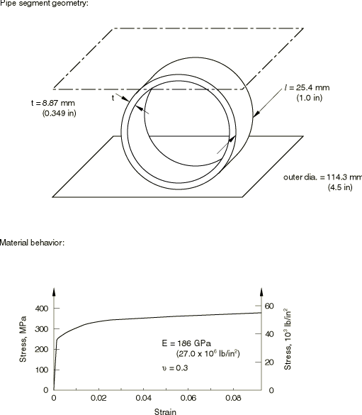
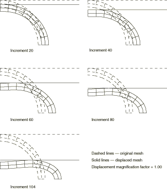
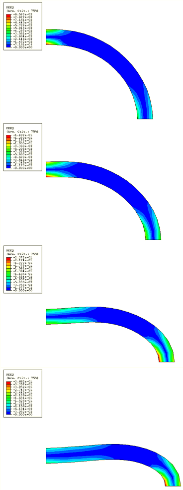
The dimensions of the pipe section segment and its material properties are shown in Figure 1. By symmetry only one quadrant of the pipe section needs to be modeled. A uniform mesh of fully integrated 8-node, plane strain, “hybrid” elements is used, with two elements through the thickness and eight around the pipe quadrant. No mesh convergence studies have been performed, but the reasonable agreement with experimental results suggests that the mesh is adequate to predict the overall response with usable accuracy.
The contact between the pipe and a flat, rigid anvil is modeled with a contact pair. The outside surface of the pipe is specified using a surface definition. The rigid anvil is modeled as an analytical rigid surface using a surface definition and a rigid body constraint. The mechanical interaction between the contact surfaces is assumed to be frictionless. The pipe is crushed by pushing down on the rigid anvil using a boundary condition to prescribe a downward vertical displacement.
In addition to the plane strain models, a continuum shell element model is provided for illustrative purposes. This model uses a uniform mesh of SC8R elements, with four elements stacked through the thickness and sixteen elements around the pipe quadrant. The anvil is modeled using continuum shell elements and then converted to a rigid body. No mesh convergence studies have been performed, since the results provide reasonable agreement with the experimental results. This model is more costly than the plane strain model since it uses more degrees of freedom.


