Problem description
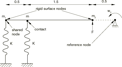
Figure 1 shows the geometry of the system considered. A single rigid body is under the action of two springs, with one attached to the rigid body and the other in contact with the rigid body. A point load is also applied to the rigid body. The rigid body is constrained at the reference node to undergo planar motion. Several two-dimensional and three-dimensional analyses based on this geometry are performed. For all cases a dummy continuum element is used to control the time incrementation.
In the first problem only rotation about the out-of-plane axis is allowed at the reference node and all the translational degrees of freedom are constrained. The inertial properties of the rigid body are represented with mass 20 and inertia about the axis normal to the plane of motion 65 at the reference node. The two springs each have a stiffness equal to 1.0 × 10⁶. The mass, m, where the spring node comes in contact with the rigid body, is 5. The force applied, F, is 1.0 × 10⁵. The initial angular velocity of the rigid body, , is 10. The end of the spring that is in contact with the rigid body has an initial velocity such that contact is already established at time 0. The various quantities above are in a consistent set of units.
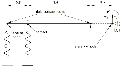
A variation of the first problem is considered (see Figure 2) in which the rigid body reference node location does not correspond to the center of mass of the rigid body. Point masses are specified on the rigid body surface nodes, 10, 10 (in three dimensions the surface node masses are each 5 since there are twice as many surface nodes); and the rotary inertia and the mass elements at the reference node are removed. The magnitude of the point masses is chosen such that the moment of inertia of the rigid body about the location of the pin constraint is the same as in the original problem; thus, the analytical solution for the rotational response is also the same.
Another variation of the original problem considered here, shown in Figure 3, is to allow translation parallel to the spring elements in addition to the rotation about the out-of-plane axis. The force applied is changed to −1.0 × 10⁵; the initial angular velocity, , is 10; and the initial velocity, , is 15. The initial velocity for the spring node in contact is chosen such that contact is already established at time 0.
A final variation of the problem is obtained by replacing the mass element and inertia element specified at the reference node with the surface masses forming the problem shown in Figure 4. The analytical solutions for the two active degrees of freedom are not the same for the last two problems since the reference node is allowed to translate.


