Oblique shock reflections

This example illustrates the use of the ideal gas equation of state model and adaptive meshing in modeling shock wave interaction problems that involve both regular and Mach reflection processes.

This page discusses:

ProductsAbaqus/Explicit

Problem description

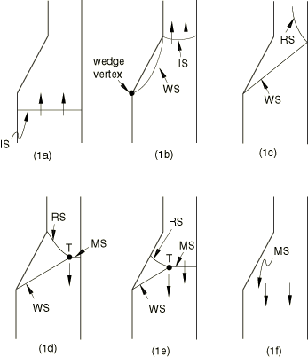
A plane shock wave in a gas with negligible viscosity and heat conductivity travels with constant velocity through a two-dimensional channel and encounters a wedge-shaped obstruction on the left wall (Amsden and Ruppel, 1981). A sequence of reflections occurs, depicted qualitatively in Figure 1(a) through Figure 1(e). The event is governed by the theory of regular shock reflection (Harlow and Amdsen, 1971). Figure 1(a) shows the incident shock wave (IS) moving through the channel toward the wedge. A shock wave (WS) is reflected from the wedge as shown in Figure 1(b). The flow Mach number and wedge angle are such that the shock remains attached at the wedge vertex. The wave configuration grows until the reflected shock strikes the right wall of the channel and is reflected back into the channel, as shown in Figure 1(c) (RS). Since the strength and angle of the incident shock wave (IS) are in the Mach reflection regime, a third shock called the Mach stem is formed (MS in Figure 1(d)). The intersection of the three shocks is called the triple point (T). This configuration cannot remain steady, and the Mach stem moves upstream against the incoming flow (Figure 1(e)) and eventually engulfs it, as shown in Figure 1(f).

The wedge half-angle is taken to be 15.13° in this example. A schematic of the model is shown in Figure 2; the model consists of two compartments separated by a diaphragm. Both compartments are filled with the same gas, at different initial states and velocities. The compartments are meshed with CPE4R elements. The left wall of the channel is modeled by a fixed analytical rigid surface, while the right wall is simulated by prescribing a symmetry boundary condition. The Abaqus/Explicit ideal gas equation of state model is used with a gas constant of 0.2 and a constant specific heat at constant volume of 0.5. These constants are not intended to represent any real gases. The gas in compartment A is initially at a unit density, a very small pressure, and zero velocity. Behind the incident shock in compartment B, a high energy gas with an initial density of 6 and an initial pressure stress of 1.2 flows toward compartment A at an initial velocity of 1.0. The diaphragm separating the compartments is removed instantaneously, causing a shock wave to propagate into compartment B.
Adaptive meshing

An elongated Eulerian adaptive mesh domain is used. The wedge-shaped obstruction is located in the middle portion of the domain where the shock refections take place. The Eulerian inflow and outflow boundaries are located far enough upstream and downstream from the obstruction to prevent undesired reflections. The mesh for the middle portion of the domain is held in place for the purpose of showing results by applying adaptive mesh constraints at the entry and exit planes of this subdomain. These constraints are in addition to spatial adaptive mesh constraints used at the Eulerian boundaries. Because the gas flow is substantial, the intensity of adaptive meshing must be increased to provide an accurate solution. The value of the MESH SWEEPS parameter is increased from the default of 1 to 5.

Results and discussion

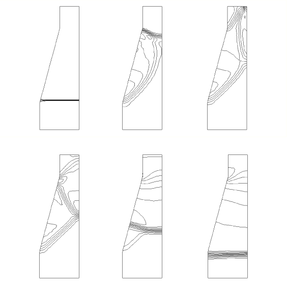
The analysis is carried out over a time of 150. The vector plots of the velocity resultant in the middle portion of the domain are shown in Figure 3. From left to right the plots are at times t=0, 12, 17, 30, 90, and 120. The corresponding contour plots of the pressure stress are given in Figure 4. The maximum value of pressure stress increased from the initial value of 1.2 to approximately 7.0 at the end of the analysis. The theory of regular reflection predicts that the half-angle of the wedge shock MS should be 48.5°. A measurement of pressure contour lines at intermediate times in Figure 4 is in good agreement with this value.

References

  1. Amsden A. A. and HMRuppel, SALE-3D: A Simplified ALE Computer Program for Calculating Three-Dimensional Fluid Flow,” Los Alamos Scientific Laboratory, 1981.
  2. Harlow F. H. and AAAmsden, Fluid Dynamics – A LASL Monograph,” Los Alamos Scientific Laboratory report LA-4700, 1971.

Figures

Figure 1. The sequence of shock reflections occurring when a plane shock wave encounters a wedge-shaped obstruction in a two-dimensional channel.

Figure 2. Schematic drawing of the model (CPE4R elements).

Figure 3. Vector plots of the velocity resultant in the middle portion of the domain for different intermediate times.

Figure 4. Pressure contours corresponding to the velocity resultant shown in the figure above.