This problem illustrates the accuracy of shell and beam finite
element solutions for bending of warped structures.
The responses of both a thick and thin twisted cantilever beam
subjected to either an in-plane or out-of-plane shear load are obtained. The
test was proposed by MacNeal and Harder (1985), who provided the analytical
solution for the thick twisted beam. The reference solution for the thin
twisted beam was provided by Simo et al. (1989).
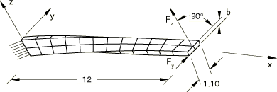
The structure is a cantilever beam, 12.0 in long and 1.1 in wide, that
twists 90° from end to end, as shown in
Figure 1.
The beam is aligned with the x-axis. Its thickness,
b, is 0.32 in for the thick case and 0.05 in for the thin
case.
The beam is modeled in
Abaqus/Standard
with 4-node shell elements (S4, S4R, and S4R5), 3-node shell elements (S3R and STRI3), quadratic shell elements (STRI65, S8R, S8R5, and S9R5), continuum shell elements (SC8R), and beam elements (B31, B32, and B33). Three mesh densities are considered for each element type. The
coarsest mesh of 4-node shell elements (2 × 12 with a warp angle of 7.5° per
element length) is illustrated in
Figure 1.
The 3-node shell mesh has the same number of elements as the equivalent 4-node
shell mesh. The quadratic shell mesh has half as many elements in each
direction (in general, the same number of degrees of freedom) as the
corresponding linear shell mesh. The coarsest mesh of beam elements uses 12
linear elements.
The beam is modeled in
Abaqus/Explicit
with a 2 × 12 mesh of S4R, S4RS, or S4RSW elements.
The material is steel with a Young's modulus of 29.0 Msi and a Poisson's
ratio of 0.22. A point load of 1.0 lb is applied at the center of the free end
in the y- and z-directions,
respectively.
Results and discussion
The results are listed in
Table 1
to
Table 12.
The tip displacements in the load directions are compared with the analytical
solution.
Abaqus/Standard
results
The shell element models all converge to the analytical solution for both
load cases and thicknesses. Even for the coarsest meshes, where for the 4-node
shells the warp angle is 7.5° per element, the results are in good agreement.
The 4-node quadrilateral results are listed in
Table 1
and
Table 2,
the 3-node triangular results are listed in
Table 5
and
Table 6,
and the second-order shell results are listed in
Table 7
and
Table 8.
For the coarsest meshes the first-order shell results are somewhat better for
the in-plane than for the out-of-plane loading case. The out-of-plane loading
case causes in-plane bending deformation at the built-in end, where the maximum
bending moments occur (refer to
Figure 1).
First-order triangular and reduced-integration quadrilateral elements require
mesh refinement to model this in-plane bending accurately. The first-order
fully integrated shell, S4, and the second-order reduced-integration elements capture the
correct in-plane bending behavior.
The continuum shell results are listed in
Table 3
and
Table 4
for both load cases and thicknesses. Results are compared for cases in which 1,
2, 4, and 8 elements are stacked in the thickness direction. For the case with
a single element stacked in the thickness direction, the results show
excessively large displacements. This may be due to the element's poor
treatment of drill stiffness. The results show good agreement for cases with
multiple elements (even two elements) stacked in the thickness direction.
The beam element models accurately reproduce the analytical result for both
load cases and thicknesses; see
Table 9
and
Table 10.
Since the coarsest mesh is sufficiently refined to capture the analytical
solution, the results do not improve with mesh refinement.
Abaqus/Explicit
results
Figure 2
shows the time history of the tip displacement and various energies for the
in-plane shear load case when the beam has a thickness of 0.32 in. The tip
displacement values indicated in the tabulated results are the displacement
values at node 132 in the direction of the applied tip load.
Table 11
and
Table 12
compare the solutions obtained with elements S4R, S4RS, and S4RSW. The response of S4RS is quite similar to that of S4R.
MacNeal, R.H., and R. L. Harder, “A
Proposed Standard Set of Problems to Test Finite Element
Accuracy,” Finite Elements in Analysis
Design, vol. 11, pp. 3–20, 1985.
Simo, J.C., D. D. Fox, and M. S. Rifai, “On
a Stress Resultant Geometrically Exact Shell Model. Part II: The Linear Theory;
Computational Aspects,” Computational Methods
in Applied Mechanical
Engineering, vol. 73, pp. 53–92, 1989.
Tables
Table 1. Tip displacements for 4-node shell meshes, thick case
(b = 0.32 in).
Loading
In-plane (
= 1.0 lb)
Out-of-plane (
= 1.0 lb)
Reference solution
5.424 × 10⁻³ (in)
1.754 × 10⁻³ (in)
Element
Mesh
FE solution
% error
FE solution
% error
S4
2 × 12
5.440 × 10⁻³
0.29
1.730 × 10⁻³
−1.37
4 × 24
5.428 × 10⁻³
0.07
1.747 × 10⁻³
−0.40
8 × 48
5.427 × 10⁻³
0.05
1.753 × 10⁻³
−0.06
S4R
2 × 12
5.479 × 10⁻³
1.01
1.868 × 10⁻³
6.50
4 × 24
5.437 × 10⁻³
0.24
1.777 × 10⁻³
1.31
8 × 48
5.430 × 10⁻³
0.11
1.761 × 10⁻³
0.40
S4R5
2 × 12
5.443 × 10⁻³
0.35
1.879 × 10⁻³
7.10
4 × 24
5.418 × 10⁻³
−0.10
1.768 × 10⁻³
0.78
8 × 48
5.416 × 10⁻³
−0.15
1.755 × 10⁻³
0.05
Table 2. Tip displacements for 4-node shell meshes, thin case
(b = 0.05 in).
Loading
In-plane (
= 1.0 lb)
Out-of-plane (
= 1.0 lb)
Reference solution
1.390 (in)
0.3431 (in)
Element
Mesh
FE solution
% error
FE solution
% error
S4
2 × 12
1.391
0.07
0.3397
−0.99
4 × 24
1.388
−0.14
0.3421
−0.29
8 × 48
1.388
−0.14
0.3427
−0.12
S4R
2 × 12
1.394
0.28
0.3403
−0.81
4 × 24
1.389
−0.07
0.3422
−0.26
8 × 48
1.388
−0.14
0.3428
−0.09
S4R5
2 × 12
1.389
−0.07
0.3388
−1.25
4 × 24
1.387
−0.22
0.3418
−0.38
8 × 48
1.387
−0.22
0.3426
−0.15
Table 3. Tip displacements for continuum shell meshes, thick case
(b = 0.32 in).
Loading
In-plane (
= 1.0 lb)
Out-of-plane (
= 1.0 lb)
Reference solution
5.424 × 10⁻³ (in)
1.754 × 10⁻³ (in)
Element
Mesh
FE solution
% error
FE solution
% error
SC8R
2 × 12 × 1
7.819 × 10⁻³
44.2
2.428 × 10⁻³
38.4
2 × 12 × 2
5.254 × 10⁻³
–3.13
1.887 × 10⁻³
7.59
2 × 12 × 4
5.352 × 10⁻³
–1.33
1.874 × 10⁻³
6.82
2 × 12 × 8
5.410 × 10⁻³
–0.27
1.873 × 10⁻³
6.79
4 × 24 × 1
7.696 × 10⁻³
41.9
2.388 × 10⁻³
36.2
4 × 24 × 2
5.229 × 10⁻³
–3.59
1.798 × 10⁻³
2.53
4 × 24 × 4
5.349 × 10⁻³
–1.38
1.777 × 10⁻³
1.28
4 × 24 × 4
5.395 × 10⁻³
–0.53
1.775 × 10⁻³
1.17
8 × 48 × 1
7.635 × 10⁻³
40.8
2.380 × 10⁻³
35.7
8 × 48 × 2
5.220 × 10⁻³
–3.76
1.781 × 10⁻³
1.54
8 × 48 × 4
5.331 × 10⁻³
–1.72
1.781 × 10⁻³
0.3
8 × 48 × 8
5.393 × 10⁻³
–0.57
1.757 × 10⁻³
0.19
Table 4. Tip displacements for continuum shell meshes, thin case
(b = 0.05 in).
Loading
In-plane (
= 1.0 lb)
Out-of-plane (
= 1.0 lb)
Reference solution
1.390 (in)
0.3431 (in)
Element
Mesh
FE solution
% error
FE solution
% error
SC8R
2 × 12 × 1
1.927
38.6
0.5826
69.8
2 × 12 × 2
1.347
–3.09
0.3574
4.17
2 × 12 × 4
1.366
–1.73
0.3412
–0.55
2 × 12 × 8
1.378
–0.86
0.3384
–1.37
4 × 24 × 1
1.908
37.3
0.5828
69.9
4 × 24 × 2
1.346
–3.17
0.3608
5.16
4 × 24 × 4
1.368
–1.58
0.3451
0.58
4 × 24 × 4
1.381
–0.65
0.3423
–0.23
8 × 48 × 1
1.903
36.9
0.5829
69.9
8 × 48 × 2
1.346
–3.17
0.3617
5.42
8 × 48 × 4
1.368
–1.58
0.3461
0.87
8 × 48 × 8
1.382
–0.59
0.3433
0.06
Table 5. Tip displacements for 3-node shell meshes, thick case
(b = 0.32 in).
Loading
In-plane (
= 1.0 lb)
Out-of-plane (
= 1.0 lb)
Reference solution
5.424 × 10⁻³ (in)
1.754 × 10⁻³ (in)
Element
Mesh
FE solution
% error
FE solution
% error
S3R
4 × 6
5.262 × 10⁻³
−2.99
1.400 × 10⁻³
−20.18
8 × 12
5.361 × 10⁻³
−1.16
1.581 × 10⁻³
−9.86
16 × 24
5.405 × 10⁻³
−0.35
1.696 × 10⁻³
−3.31
STRI3
4 × 6
5.323 × 10⁻³
−1.86
1.438 × 10⁻³
−18.01
8 × 12
5.359 × 10⁻³
−1.20
1.594 × 10⁻³
−9.18
16 × 24
5.386 × 10⁻³
−0.70
1.698 × 10⁻³
−3.19
Table 6. Tip displacements for 3-node shell meshes, thin case
(b = 0.05 in).
Loading
In-plane (
= 1.0 lb)
Out-of-plane (
= 1.0 lb)
Reference solution
1.390 (in)
0.3431 (in)
Element
Mesh
FE solution
% error
FE solution
% error
S3R
4 × 6
1.352
−2.73
0.3251
−5.25
8 × 12
1.372
−1.29
0.3381
−1.46
16 × 24
1.383
−0.50
0.3417
−0.41
STRI3
4 × 6
1.383
−0.50
0.3382
−1.43
8 × 12
1.384
−0.43
0.3413
−0.52
16 × 24
1.386
−0.29
0.3424
−0.20
Table 7. Tip displacements for quadratic shell meshes, thick case
(b = 0.32 in).
Loading
In-plane (
= 1.0 lb)
Out-of-plane (
= 1.0 lb)
Reference solution
5.424 × 10⁻³ (in)
1.754 × 10⁻³ (in)
Element
Mesh
FE solution
% error
FE solution
% error
STRI65
2 × 6
5.408 × 10⁻³
−0.29
1.751 × 10⁻³
−0.17
4 × 12
5.412 × 10⁻³
−0.22
1.752 × 10⁻³
−0.11
8 × 24
5.414 × 10⁻³
−0.18
1.752 × 10⁻³
−0.11
S8R
1 × 6
5.376 × 10⁻³
−0.88
1.745 × 10⁻³
−0.51
2 × 12
5.411 × 10⁻³
−0.24
1.752 × 10⁻³
−0.11
4 × 24
5.415 × 10⁻³
−0.17
1.752 × 10⁻³
−0.11
S8R5 & S9R5
1 × 6
5.405 × 10⁻³
−0.35
1.746 × 10⁻³
−0.46
2 × 12
5.413 × 10⁻³
−0.20
1.752 × 10⁻³
−0.11
4 × 24
5.416 × 10⁻³
−0.15
1.753 × 10⁻³
−0.06
Table 8. Tip displacements for quadratic shell meshes, thin case
(b = 0.05 in).
Loading
In-plane (
= 1.0 lb)
Out-of-plane (
= 1.0 lb)
Reference solution
1.390 (in)
0.3431 (in)
Element
Mesh
FE solution
% error
FE solution
% error
STRI65
2 × 6
1.384
−0.43
0.3420
−0.32
4 × 12
1.384
−0.43
0.3429
−0.06
8 × 24
1.386
−0.29
0.3429
−0.06
S8R
1 × 6
1.214
−12.66
0.3311
−3.50
2 × 12
1.379
−0.79
0.3427
−0.11
4 × 24
1.387
−0.22
0.3429
−0.05
S8R5 & S9R5
1 × 6
1.386
−0.29
0.3423
−0.23
2 × 12
1.387
−0.22
0.3429
−0.05
4 × 24
1.387
−0.21
0.3429
−0.05
Table 9. Tip displacements for beam meshes, thick case (b =
0.32 in).
Loading
In-plane (
= 1.0 lb)
Out-of-plane (
= 1.0 lb)
Reference solution
5.424 × 10⁻³ (in)
1.754 × 10⁻³ (in)
Element
Mesh
FE solution
% error
FE solution
% error
B31
12
5.422 × 10⁻³
−0.04
1.753 × 10⁻³
−0.06
24
5.428 × 10⁻³
0.07
1.750 × 10⁻³
−0.23
48
5.429 × 10⁻³
0.09
1.750 × 10⁻³
−0.23
B32
6
5.429 × 10⁻³
0.09
1.750 × 10⁻³
−0.23
12
5.429 × 10⁻³
0.09
1.750 × 10⁻³
−0.23
24
5.429 × 10⁻³
0.09
1.750 × 10⁻³
−0.23
B33
12
5.430 × 10⁻³
0.11
1.743 × 10⁻³
−0.63
24
5.429 × 10⁻³
0.09
1.743 × 10⁻³
−0.63
48
5.428 × 10⁻³
0.07
1.743 × 10⁻³
−0.63
Table 10. Tip displacements for beam meshes, thin case (b =
0.05 in).
Loading
In-plane (
= 1.0 lb)
Out-of-plane (
= 1.0 lb)
Reference solution
1.390 (in)
0.3431 (in)
Element
Mesh
FE solution
% error
FE solution
% error
B31
12
1.392
0.15
0.3438
0.26
24
1.394
0.29
0.3430
−0.03
48
1.394
0.29
0.3428
−0.03
B32
6
1.394
0.29
0.3427
−0.03
12
1.394
0.29
0.3427
−0.03
24
1.394
0.29
0.3427
−0.03
B33
12
1.395
0.36
0.3417
−0.32
24
1.395
0.36
0.3418
−0.32
48
1.395
0.36
0.3421
−0.32
Table 11. Tip displacements for 4-node shell 2 x 12 mesh in
Abaqus/Explicit,
thick case (b = 0.32 in).
Loading
In-plane (
= 1.0 lb)
Out-of-plane (
= 1.0 lb)
Reference solution
5.424 × 10⁻³ (in)
1.754 × 10⁻³ (in)
Element
Mesh
FE solution
% error
FE solution
% error
S4R
2 × 12
5.542 x 10⁻³
2.18
1.800 × 10⁻³
2.62
S4RS
2 × 12
5.438 × 10⁻³
2.57
1.802 × 10⁻³
2.74
S4RSW
2 × 12
5.435 × 10⁻³
0.20
1.869 × 10⁻³
6.56
Table 12. Tip displacements for 4-node shell 2 x 12 mesh in
Abaqus/Explicit,
thin case (b = 0.05 in).
Loading
In-plane (
= 1.0 lb)
Out-of-plane (
= 1.0 lb)
Reference solution
1.390 (in)
0.3431 (in)
Element
Mesh
FE solution
% error
FE solution
% error
S4R
2 × 12
1.366
-1.73
0.3443
0.35
S4RS
2 × 12
1.376
-1.01
0.3390
−1.19
S4RSW
2 × 12
1.424
2.45
0.3821
11.37
Figures
Figure 1. Twisted beam. Figure 2. Variation of
at node 132 with time,
Abaqus/Explicit
analysis. Figure 3. Energy variation with time,
Abaqus/Explicit
analysis.