Variable thickness shells and membranes

This example illustrates the use of shell and membrane elements in models defined with variable thickness.

This page discusses:

ProductsAbaqus/StandardAbaqus/Explicit

Problem description

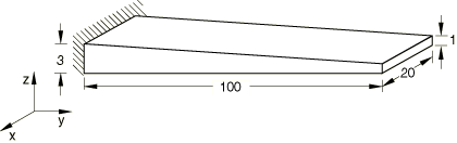
For the general shell, membrane, and continuum shell elements the model consists of a tapered plate of length 100 and width 20, as shown in Figure 1. The plate is clamped at one end, and the thickness varies linearly across the plate from 3 at the clamped end to 1 at the free end. The model consists of 10 elements along the length and 2 across the width. For the model using continuum shell elements the thickness is defined by the nodal geometry.

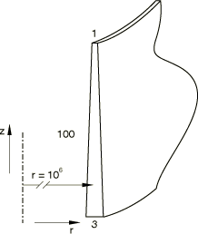
For the axisymmetric elements the model consists of a tapered cylinder, with a radius of 1 × 10⁶ and a length of 100, as shown in Figure 2. The cylinder is clamped at one end, and the thickness varies linearly along the length of the cylinder from 3 at the clamped end to 1 at the free end. The radius is chosen to be very large to ensure that the effects of circumferential stresses are negligible. The cylinder is meshed with 10 elements.

A linear elastic material with a Young's modulus of 10 × 109, a Poisson's ratio of 0, and a density of 8000 is used for all the tests. The thicker ends of the plate and cylinder are fully clamped. The shell elements are loaded with a bending moment of 3 per unit length at the thin end of the shell, and the membrane elements are loaded with an in-plane force of 50 per unit length at the thin end of the membrane.

Results and discussion

The Abaqus/Standard results for shell and continuum shell elements are shown in Table 1. The Abaqus/Explicit results for shell and continuum shell elements are shown in Table 2 and for membrane elements in Table 3. The differences in the Abaqus/Explicit results are due to dynamic effects and mesh discretization. For the shell elements in Abaqus/Explicit the results using a shell offset with a value of 0.5 are also shown in Table 2.

Input files

Abaqus/Standard input files

varthick_std_s3r.inp

S3R element using SHELL SECTION to define section properties.

varthick_std_s4r.inp

S4R element using SHELL SECTION to define section properties.

varthick_std_s4r_edmom.inp

S4R element using SHELL SECTION to define section properties. Bending moment applied with a distributed edge moment.

varthick_std_sc6r.inp

SC6R element using SHELL SECTION to define section properties.

varthick_std_sc6r_sgs.inp

SC6R element using SHELL GENERAL SECTION to define section properties.

varthick_std_sc8r.inp

SC8R element using SHELL SECTION to define section properties.

varthick_std_sc8r_sgs.inp

SC8R element using SHELL GENERAL SECTION to define section properties.

varthick_std_sc8r_eh.inp

SC8R element with enhanced hourglass control using SHELL SECTION to define section properties.

varthick_std_sc8r_sgs_eh.inp

SC8R element with enhanced hourglass control using SHELL GENERAL SECTION to define section properties.

varthick_std_css8.inp

CSS8 element.

Abaqus/Explicit input files

varthick_s3r.inp

S3R element.

varthick_s3r_offset.inp

S3R element and a shell offset.

varthick_s4r.inp

S4R element.

varthick_s4r_offset.inp

S4R element and a shell offset.

varthick_sc6r.inp

SC6R element.

varthick_sc8r.inp

SC8R element.

varthick_sc6r_sgs.inp

SC6R element using SHELL GENERAL SECTION to define section properties.

varthick_sc8r_sgs.inp

SC8R element using SHELL GENERAL SECTION to define section properties.

varthick_sax1.inp

SAX1 element.

varthick_sax1_offset.inp

SAX1 element and a shell offset.

varthick_m3d3.inp

M3D3 element.

varthick_m3d4r.inp

M3D4R element.

varthick_m3d4r_hgc.inp

COMBINED hourglass option for membrane elements included for the sole purpose of testing the performance of the code.

varthick_m3d4r_hgv.inp

VISCOUS hourglass option for membrane elements included for the sole purpose of testing the performance of the code.

Tables

Table 1. Abaqus/Standard shell bending results.
Element Type Tip Displacement (uz) Tip Rotation
EXACT 2.00 × 10⁻⁶ 8.00 × 10⁻⁸
S3R 2.06 × 10⁻⁶ 8.09 × 10⁻⁸
S4R 2.02 × 10⁻⁶ 7.91 × 10⁻⁸
SC6R 1.93 × 10⁻⁶  
SC6R (sgs) 1.93 × 10⁻⁶  
SC8R 2.02 × 10⁻⁶  
SC8R (sgs) 2.02 × 10⁻⁶  
SC8R* 2.02 × 10−6  
SC8R* (sgs) 2.02 × 10⁻⁶  
CSS8 2.00 × 10⁻⁶
*Abaqus/Standard results with enhanced hourglass control.
Table 2. Abaqus/Explicit shell bending results.
Element Type Offset Value Tip Displacement (uz) Tip Rotation
EXACT   2.00 × 10⁻⁶ 8.00 × 10−8
SAX1 2.26 × 10⁻⁶ 8.33 × 10−8
SAX1 0.5 2.23 × 10⁻⁶ 8.26 × 10⁻⁸
S3R 2.26 × 10⁻⁶ 8.50 × 10⁻⁸
S3R 0.5 2.23 × 10⁻⁶ 8.38 × 10⁻⁸
S4R 2.26 × 10⁻⁶ 8.33 × 10⁻⁸
S4R 0.5 2.24 × 10⁻⁶ 8.23 × 10⁻⁸
SC6R   1.93 × 10⁻⁶  
SC8R   2.01 × 10⁻⁶  
SC6R (sgs)   1.93 × 10⁻⁶  
SC8R (sgs)   2.01 × 10⁻⁶  
Table 3. Abaqus/Explicit membrane element results.
Element Type Tip Displacement (uy)
EXACT 2.746 × 10⁻⁷
M3D3 2.751 × 10⁻⁷
M3D4R 2.742 × 10⁻⁷

Figures

Figure 1. Tapered plate for general elements.

Figure 2. Tapered cylinder.