Vibration of a rotating cantilever plate

This example verifies the centrifugal load stiffness effect present in vibration problems when the structure is undergoing small vibrations in a rotating coordinate frame.

This page discusses:

ProductsAbaqus/Standard

The most common example of vibration problems is the study of the vibrations of components of rotating machines, such as the blades on turbines and compressors. In such cases two effects that are not present in vibration problems in fixed coordinate systems become important: the initial stressing of the structure caused by the centrifugal loading and the “load stiffness” effect caused by the line of action of the centrifugal load changing if the vibration causes motion in the plane normal to the axis of rotation. In most conventional designs of rotating machines the initial stress effect is a stiffening effect, and the load stiffness effect is a softening effect. In the vibration of blades on turbines or compressors the load stiffness effect is significant only for long blades on small wheels, such as the fan blades on modern high bypass jet engines for aircraft: see Hibbitt (1979). The purpose of this example is to illustrate this effect and verify the capability in Abaqus for such vibration studies.

Problem description

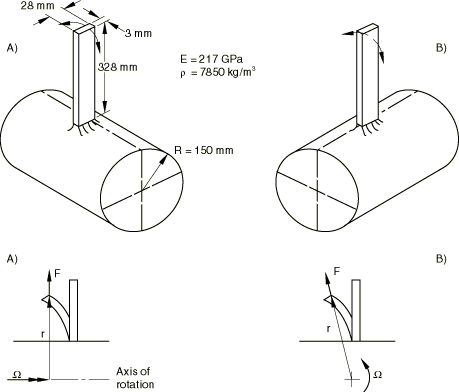
The model is a single, flat plate, 328 mm long, 28 mm wide, and 3 mm thick, built into a rigid wheel of 150 mm radius, spinning about its axis. Two versions of the problem are studied. In “Case A” the plate is mounted so that its first vibration mode is in the plane containing the axis of the wheel. Thus, the line of action of the centrifugal load does not change as the blade undergoes small vibrations; hence, the load stiffness effect does not participate in this mode. In “Case B” the plate is mounted so that its first vibration mode is in a plane at right angles to the axis of rotation of the wheel. Thus, the load stiffness effect is important in this mode. Since the plate is relatively long compared to the radius of the wheel, the load stiffness effect is significant: the first mode frequency is substantially lower in Case B than it is in Case A.

Several different element types are used (beams, shells, three-dimensional solid elements). In each case a “reasonable” mesh is chosen—typically six elements along the plate. Since we are comparing only the lowest mode frequency, rather coarse meshing should be adequate.

The plate is made of steel, with Young's modulus 217 GPa and a density of 7850 kg/m3.
Analysis

The analysis is done in a series of steps. Step 1 extracts the lowest mode of the system at rest (no rotation of the wheel) using the frequency procedure. In this example only the lowest frequency is required: in a practical case several frequencies would probably be needed.

Step 2 is a static procedure in which the centrifugal load, corresponding to a rotational speed of the system of 25 revolutions/second, is applied using a distributed load. This centrifugal load is applied using both the CENT and CENTRIF load types. The distributed load magnitude must be given as ρΩ2 with the CENT load type and as Ω2 with the CENTRIF load type. The CENTRIF load type uses the actual mass matrix of the element in the load calculation for the density, which means that a lumped mass matrix is used for first-order elements and a consistent mass matrix is used for second-order elements. The CENT load type always uses a consistent mass matrix. Geometric nonlinearities are considered in the step, which causes Abaqus to include the initial stress and load stiffness effects and implies a nonlinear analysis.

Step 3 uses the frequency procedure to obtain the lowest frequency at this rotational speed. Step 4 is a static step to increase the centrifugal load to a rotational speed of 50 revolutions/second, Step 5 obtains the lowest eigenmode at this speed, Step 6 increases the speed to 75 revolutions/second, and Step 7 obtains the lowest eigenmode at this speed.

Substructure analysis

This example is suitable for demonstrating the substructure preload capability in Abaqus. With this option it is possible to create a finite element mesh, load it using a nonlinear procedure, and create a substructure using the current stiffness after the loading. If the entire wheel had to be modeled with all the rotating blades, the model could be simplified by using this option. The blade would be modeled as a substructure, the centrifugal force applied, and the stiffness formed including the “load stiffness.” The substructure could then be rotated and used for all the blades attached to the wheel.

Preloading is obtained by preceding a substructure generation step with one or several analysis steps. The substructure stiffness is formed from the final loading condition of the preceding general analysis step. Four substructures are generated for each analysis. The first is generated without any preloading. The remaining three substructures are generated after a centrifugal load has been applied so that each includes the load stiffness associated with a different rotational speed. Furthermore, when the substructures are used the load stiffness is included in the substructure stiffness matrix and is, thus, included in the frequency extraction whether or not geometric nonlinearities are considered in the frequency step.

Results and discussion

The frequencies obtained in each case for each geometric model and speed are shown in Table 1, where these numerical results are compared to a Rayleigh quotient solution (Lindberg, 1986). The numerical results are very close to the Rayleigh quotient solution. The differences between the results obtained using load type CENT and load type CENTRIF are negligible.

Input files

Case A:
vibrotplate_b21_cent_a.inp

Element type B21 with the CENT loading option.

vibrotplate_b21_centrif_a.inp

Element type B21 with the CENTRIF loading option.

vibrotplate_b23_cent_a.inp

Element type B23 with the CENT loading option.

vibrotplate_b23_centrif_a.inp

Element type B23 with the CENTRIF loading option.

vibrotplate_b31_cent_a.inp

Element type B31 with the CENT loading option.

vibrotplate_b31_centrif_a.inp

Element type B31 with the CENTRIF loading option.

vibrotplate_b33_cent_a.inp

Element type B33 with the CENT loading option.

vibrotplate_b33_centrif_a.inp

Element type B33 with the CENTRIF loading option.

vibrotplate_c3d8i_cent_a.inp

Element type C3D8I with the CENT loading option.

vibrotplate_c3d8i_centrif_a.inp

Element type C3D8I with the CENTRIF loading option.

vibrotplate_c3d10_cent_a.inp

Element type C3D10 with the CENT loading option.

vibrotplate_c3d10_centrif_a.inp

Element type C3D10 with the CENTRIF loading option.

vibrotplate_c3d10hs_cent_a.inp

Element type C3D10HS with the CENT loading option.

vibrotplate_c3d10hs_centrif_a.inp

Element type C3D10HS with the CENTRIF loading option.

vibrotplate_c3d10m_cent_a.inp

Element type C3D10M with the CENT loading option.

vibrotplate_c3d10m_centrif_a.inp

Element type C3D10M with the CENTRIF loading option.

vibrotplate_c3d20_cent_a.inp

Element type C3D20 with the CENT loading option.

vibrotplate_c3d20_centrif_a.inp

Element type C3D20 with the CENTRIF loading option.

vibrotplate_c3d20r_cent_a.inp

Element type C3D20R with the CENT loading option.

vibrotplate_c3d20r_centrif_a.inp

Element type C3D20R with the CENTRIF loading option.

vibrotplate_s8r_cent_a.inp

Element type S8R with the CENT loading option.

vibrotplate_s8r_centrif_a.inp

Element type S8R with the CENTRIF loading option.

vibrotplate_s8r5.inp

Element type S8R5 with the CENT loading option.

vibrotplate_s8r5_centrif_a.inp

Element type S8R5 with the CENTRIF loading option.

vibrotplate_s8r5_substr.inp

Element type S8R5 when the blade is modeled as a substructure with the CENT loading option.

vibrotplate_s8r5_substr_gen1.inp

Substructure generation referenced in the analysis vibrotplate_s8r5_substr.inp.

vibrotplate_s8r5_substr_centrif_a.inp

Element type S8R5 when the blade is modeled as a substructure with the CENTRIF loading option.

vibrotplate_s8r5_substr_centrif_a_gen1.inp

Substructure generation referenced in the analysis vibrotplate_s8r5_substr_centrif_a.inp.

Case B:
vibrotplate_b21_cent_b.inp

Element type B21 with the CENT loading option.

vibrotplate_b21_centrif_b.inp

Element type B21 with the CENTRIF loading option.

vibrotplate_b23_cent_b.inp

Element type B23 with the CENT loading option.

vibrotplate_b23_centrif_b.inp

Element type B23 with the CENTRIF loading option.

vibrotplate_b31_cent_b.inp

Element type B31 with the CENT loading option.

vibrotplate_b31_centrif_b.inp

Element type B31 with the CENTRIF loading option.

vibrotplate_b33_cent_b.inp

Element type B33 with the CENT loading option.

vibrotplate_b33_centrif_b.inp

Element type B33 with the CENTRIF loading option.

vibrotplate_c3d8i_cent_b.inp

Element type C3D8I with the CENT loading option.

vibrotplate_c3d8i_centrif_b.inp

Element type C3D8I with the CENTRIF loading option.

vibrotplate_c3d10_cent_b.inp

Element type C3D10 with the CENT loading option.

vibrotplate_c3d10_centrif_b.inp

Element type C3D10 with the CENTRIF loading option.

vibrotplate_c3d10hs_cent_b.inp

Element type C3D10HS with the CENT loading option.

vibrotplate_c3d10hs_centrif_b.inp

Element type C3D10HS with the CENTRIF loading option.

vibrotplate_c3d10m_cent_b.inp

Element type C3D10M with the CENT loading option.

vibrotplate_c3d10m_centrif_b.inp

Element type C3D10M with the CENTRIF loading option.

vibrotplate_c3d20_cent_b.inp

Element type C3D20 with the CENT loading option.

vibrotplate_c3d20_centrif_b.inp

Element type C3D20 with the CENTRIF loading option.

vibrotplate_c3d20r_cent_b.inp

Element type C3D20R with the CENT loading option.

vibrotplate_c3d20r_centrif_b.inp

Element type C3D20R with the CENTRIF loading option.

vibrotplate_s8r_cent_b.inp

Element type S8R with the CENT loading option.

vibrotplate_s8r_centrif_b.inp

Element type S8R with the CENTRIF loading option.

vibrotplate_s8r5_cent_b.inp

Element type S8R5 with the CENT loading option.

vibrotplate_s8r5_centrif_b.inp

Element type S8R5 with the CENTRIF loading option.

vibrotplate_s8r5_substr_cent_b.inp

Element type S8R5 when the blade is modeled as a substructure with the CENT loading option.

vibrotplate_s8r5_substr_cent_b_gen1.inp

Substructure generation referenced in the analysis vibrotplate_s8r5_substr_cent_b.inp.

vibrotplate_s8r5_substr_centrif_b.inp

Element type S8R5 when the blade is modeled as a substructure with the CENTRIF loading option.

vibrotplate_s8r5_substr_centrif_b_gen1.inp

Substructure generation referenced in the analysis vibrotplate_s8r5_substr_centrif_b.inp.

References

  1. Hibbitt H. D.Some Follower Forces and Load Stiffness,” International Journal for Numerical Methods in Engineering, vol. 14, pp. 937941, 1979.
  2. Lindberg B.Berechnung der ersten Eigenfrequenz eines Balkens in Fliehkraftfeld mit Rayleigh Quotient,” Internal report HTGE-ST-0051, Brown Boveri & Cie., Baden, Switzerland, 1986.

Tables

Table 1. Spinning beam frequencies (Hz).
  Vibration in the plane Vibration normal to
  of the rotation axis the rotation axis
  (Case A) (Case B)
Rotary speed (cycles/sec) 25 50 75 25 50 75
Rayleigh quotient 23.68 41.74 72.10 104.27 33.42 51.95 72.44
B21 23.44 41.20 71.00 102.29 32.94 50.86 70.24
B23 23.68 41.72 71.94 103.73 33.40 51.73 71.66
B31 23.44 41.20 71.00 102.29 32.94 50.86 70.24
B33 23.68 41.83 72.14 103.98 33.54 52.00 72.02
S8R 23.89 41.90 72.13 103.91 33.63 51.99 71.91
S8R5 23.81 41.82 72.05 103.82 33.53 51.87 71.79
Substructure 23.82 41.88 72.33 104.58 33.56 51.98 72.04
C3D8I 24.23 41.90 71.93 103.66 33.82 52.15 72.25
C3D10 25.14 42.70 72.88 104.91 34.62 53.03 73.34
C3D10HS 25.14 42.71 72.89 104.92 34.63 53.04 73.37
C3D10M 24.82 42.40 72.51 104.45 34.32 52.70 72.96
C3D20 24.53 42.45 72.87 105.02 34.30 53.01 73.51
C3D20R 24.28 42.25 72.54 104.38 34.06 52.55 72.60

Figures

Figure 1. Plate and wheel geometry.