Problem description
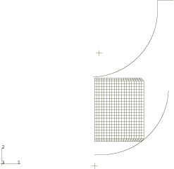
Three different geometric models are considered, as shown in Figure 1. Each model consists of a rigid punch, a rigid die, and a deformable blank. The outer top and bottom edges of the blank are cambered, which facilitates the flow of material against the tools. The punch and die have semicircular cross-sections; the punch has a radius of 68.4 mm, and the die has a radius of 67.9 mm. The blank is modeled as a von Mises elastic, perfectly plastic material with a Young's modulus of 4000 MPa and a yield stress of 5 MPa. The Poisson's ratio is 0.21; the density is 1.E−4 tonne/mm3.
In each case the punch is moved 61 mm, while the die is fully constrained. A smooth amplitude curve is used to ramp the punch velocity to a maximum, at which it remains constant. The smoothing of the velocity promotes a quasi-static response to the loading.
Case 1: Axisymmetric model for cup forming
The blank is meshed with CAX4R elements and measures 50 × 64.77 mm. The punch and the die are modeled as analytical rigid surfaces using connected line segments. Symmetry boundary conditions are prescribed at r=0. The finite element model is shown in Figure 2.
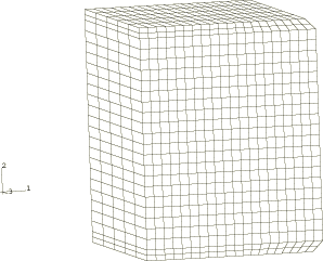
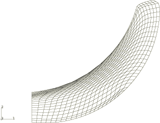
Case 2: Three-dimensional model for trough forming
The blank is meshed with C3D8R elements and measures 50 × 64.7 × 64.7 mm. The punch and the die are modeled as three-dimensional cylindrical analytical rigid surfaces. Symmetry boundary conditions are applied at the x=0 and z=0 planes. The finite element model of the blank is shown in Figure 3.
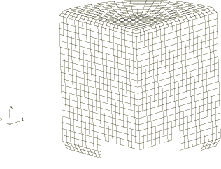
Case 3: Three-dimensional model for cup forming
The blank is meshed with C3D8R elements. A 90° wedge of the blank with a radius of 50 mm and a height of 64.7 mm is analyzed. The punch and the die are modeled as three-dimensional revolved analytical rigid surfaces. Symmetry boundary conditions are applied at the x=0 and y=0 planes. The finite element model of the blank is shown in Figure 4.