Problem description
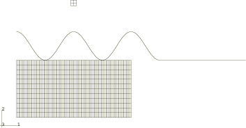
Three different geometric models are considered, as shown in Figure 1. Each model consists of a rigid die and a deformable blank. The cross-sectional shape of the die is sinusoidal with an amplitude and a period of 5 and 10 mm, respectively. The blank is steel and is modeled as a von Mises elastic-plastic material with a Young's modulus of 200 GPa, an initial yield stress of 100 MPa, and a constant hardening slope of 300 MPa. Poisson's ratio is 0.3; the density is 7800 kg/m3.
In all cases the die is moved downward vertically at a velocity of 2000 mm/sec and is constrained in all other degrees of freedom. The total die displacement is 7.6 mm for Case 1, 6.7 mm for Case 2, and 5.6 mm for Case 3. These displacements represent the maximum possible given the refinement and topology of the initial mesh (if the quality of the mesh is retained for the duration of the analysis). Although each analysis uses a sinusoidal die, the geometries and flow characteristics of the blank material are quite different for each problem.
Case 1: Axisymmetric model
The blank is meshed with CAX4R elements and measures 20 × 10 mm. The dies are modeled as analytical rigid surfaces comprised of connected line segments. The bottom of the blank is constrained in the z-direction, and symmetry boundary conditions are prescribed at r=0. The initial configuration of the blank and the die is shown in Figure 2.
Case 2: Three-dimensional model
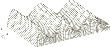
The blank is meshed with C3D8R elements and measures 20 × 10 × 10 mm. The dies are modeled as three-dimensional cylindrical analytical rigid surfaces. The bottom of the blank is constrained in the y-direction, and symmetry boundary conditions are applied at the x=0 and z=10 planes. The finite element model of the blank and the die is shown in Figure 3.
Case 3: Three-dimensional model
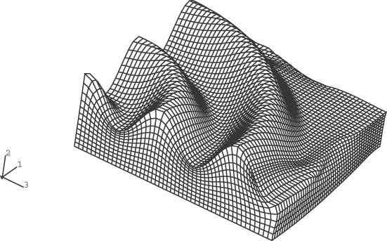
The blank is meshed with C3D8R elements and measures 20 × 10 × 20 mm. The dies are modeled as three-dimensional revolved analytical rigid surfaces. The bottom of the blank is constrained in the y-direction, and symmetry boundary conditions are applied at the x=0 and z=10 planes. The finite element model of the blank and the die is shown in Figure 4. The revolved die is displaced upward in the figure from its initial position for clarity.