Problem description
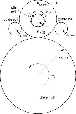
Ring rolling is a specialized process typically used to manufacture parts with revolved geometries such as bearings. The three-dimensional rolling setup usually includes a freely mounted, idle roll; a continuously rotating driver roll; and guide rolls in the rolling plane. Transverse to the rolling plane, conical rolls are used to stabilize the ring and provide a forming surface in the out-of-plane direction. In this example a two-dimensional, plane stress idealization is used that ignores the effect of the conical rolls. A schematic diagram of the ring and the surrounding tools is shown in Figure 1.
The driver roll has a diameter of 680 mm, and the idle and guide rolls have diameters of 102 mm. The ring has an initial inner diameter of 127.5 mm and a thickness of 178.5 mm. The idle and driver rolls are arranged vertically and are in contact with the inner and outer surfaces of the ring, respectively. The driver roll is rotated around its stationary axis, while the idle roll is moved vertically downward at a specified feed rate. For this simulation the x–y motion of the guide rolls is determined a priori and is prescribed so that the rolls remain in contact with the ring throughout the analysis but do not exert appreciable force on it. In practice the guide rolls are usually connected through linkage systems, and their motion is a function of both force and displacement.
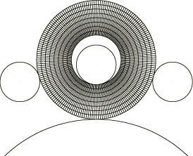
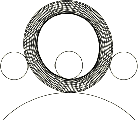
The ring is meshed with CPS4R elements, as shown in Figure 2. The ring is steel and is modeled as a von Mises elastic-plastic material with a Young's modulus of 150 GPa, an initial yield stress of 168.7 MPa, and a constant hardening slope of 884 MPa. The Poisson's ratio is 0.3; the density is 7800 kg/m3.
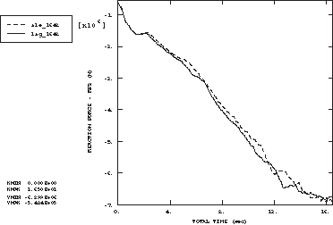
The analysis is run so that the ring completes approximately 20 revolutions (16.5 seconds). The rigid rolls are modeled as analytical rigid surfaces using connected line segments. The driver roll is rotated at a constant angular velocity of 3.7888 rad/sec about the z-axis, while the idle roll has a constant feed rate of 4.9334 mm/sec and is free to rotate about the z-axis. All other degrees of freedom for the driver and idle rolls are constrained. A friction coefficient of 0.5 is defined at the blank-idle roll and blank-drive roll interfaces. Frictionless contact is used between the ring and guide rolls, and the rotation of the guide rolls is constrained since the actual guide rolls are free to rotate and exert negligible torque on the ring.
To obtain an economical solution, the masses of all elements in the ring are scaled by a factor of 2500. This scaling factor represents a reasonable upper limit on the mass scaling possible for this problem, above which significant inertial effects would be generated. Furthermore, since the two-dimensional model does not contain the conical rolls, the ring oscillates from side to side even under the action of the guide rolls. An artificial viscous pressure of 300 MPa sec/m is applied on the inner and outer surfaces of the ring to assist the guide rolls in preserving the circular shape of the ring. The pressure value was chosen by trial and error.


