Geometry and model
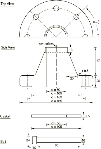
The bolted joint assembly being analyzed is depicted in Figure 1. The geometry and dimensions of the various parts are taken from Sawa et al. (1991), modified slightly to simplify the modeling. The inner wall radius of both the hub and the gasket is 25 mm. The outer wall radii of the pipe flange and the gasket are 82.5 mm and 52.5 mm, respectively. The thickness of the gasket is 2.5 mm. The pipe flange has eight bolt holes that are equally spaced in the pitch circle of radius 65 mm. The radius of the bolt hole is modified in this analysis to be the same as that of the bolt: 8 mm. The bolt head (bearing surface) is assumed to be circular, and its radius is 12 mm.
The Young's modulus is 206 GPa and the Poisson's ratio is 0.3 for both the bolt and the pipe hub/flange. The gasket is modeled with either solid continuum or gasket elements. When continuum elements are used, the gasket's Young's modulus, E, equals 68.7 GPa and its Poisson's ratio, , equals 0.3.
When gasket elements are used, a linear gasket pressure/closure relationship is used with the effective “normal stiffness,” , equal to the material Young's modulus divided by the thickness so that 27.48 GPa/mm. Similarly a linear shear stress/shear motion relationship is used with an effective shear stiffness, , equal to the material shear modulus divided by the thickness so that 10.57 GPa/mm. The membrane behavior is specified with a Young's modulus of 68.7 GPa and a Poisson's ratio of 0.3. Sticking contact conditions are assumed in all contact areas: between the bearing surface and the flange and between the gasket and the hub. Contact between the bolt shank and the bolt hole is ignored.
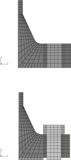
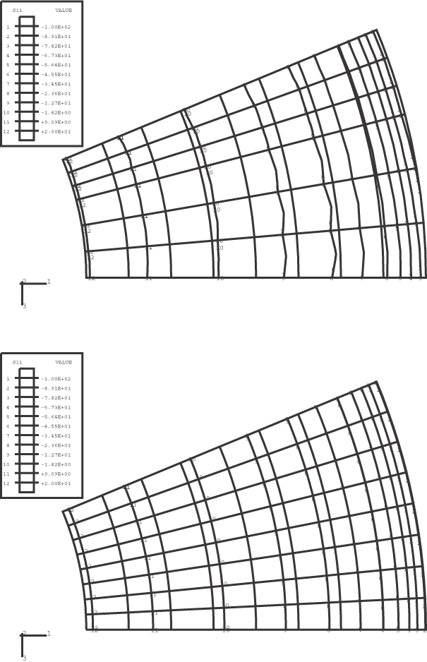
The finite element idealizations of the symmetric half of the pipe joint are shown in Figure 2 and Figure 3, corresponding to the axisymmetric and three-dimensional analyses, respectively. The mesh used for the axisymmetric analysis consists of a mesh for the pipe hub/flange and gasket and a separate mesh for the bolts. In Figure 2 the top figure shows the mesh of the pipe hub and flange, with the bolt hole area shown in a lighter shade; and the bottom figure shows the overall mesh with the gasket and the bolt in place.
For the axisymmetric model second-order elements with reduced integration, CAX8R, are used throughout the mesh of the pipe hub/flange. The gasket is modeled with either CAX8R solid continuum elements or GKAX6 gasket elements. Contact between the gasket and the pipe hub/flange is modeled with contact pairs between surfaces defined on the faces of elements in the contact region or between such element-based surfaces and node-based surfaces. In an axisymmetric analysis the bolts and the perforated flange must be modeled properly. The bolts are modeled as plane stress elements since they do not carry hoop stress. Second-order plane stress elements with reduced integration, CPS8R, are employed for this purpose. The contact surface definitions, which are associated with the faces of the elements, account for the plane stress condition automatically. To account for all eight bolts used in the joint, the combined cross-sectional areas of the shank and the head of the bolts must be calculated and redistributed to the bolt mesh appropriately using the area attributes for the solid elements. The contact area is adjusted automatically.
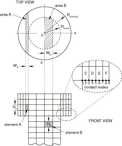
Figure 4 illustrates the cross-sectional views of the bolt head and the shank. Each plane stress element represents a volume that extends out of the x–y plane. For example, element A represents a volume calculated as () × (). Likewise, element B represents a volume calculated as () × (). The sectional area in the x–z plane pertaining to a given element can be calculated as
where R is the bolt head radius, , or the shank radius, (depending on the element location), and and are x-coordinates of the left and right side of the given element, respectively.
If the sectional areas are divided by the respective element widths, and , we obtain representative element thicknesses. Multiplying each element thickness by eight (the number of bolts in the model) produces the thickness values that are found in the solid section definition.
Sectional areas that are associated with bolt head elements located on the model's contact surfaces are used to calculate the surface areas of the nodes used in defining the node-based surfaces of the model. Referring again to Figure 4, nodal contact areas for a single bolt are calculated as follows:
where through are contact areas that are associated with contact nodes 1–9 and through are sectional areas that are associated with bolt head elements C–F. Multiplying the above areas by eight (the number of bolts in the model) provides the nodal contact areas found in the contact property definitions.
A common way of handling the presence of the bolt holes in the pipe flange in axisymmetric analyses is to smear the material properties used in the bolt hole area of the mesh and to use inhomogeneous material properties that correspond to a weaker material in this region. General guidelines for determining the effective material properties for perforated flat plates are found in ASME Section VIII Div 2 Article 4–9. For the type of structure under study, which is not a flat plate, a common approach to determining the effective material properties is to calculate the elasticity moduli reduction factor, which is the ratio of the ligament area in the pitch circle to the annular area of the pitch circle. In this model the annular area of the pitch circle is given by 6534.51 mm2, and the total area of the bolt holes is given by 1608.5 mm2. Hence, the reduction factor is simply 0.754. The effective in-plane moduli of elasticity, and , are obtained by multiplying the respective moduli, and , by this factor. We assume material isotropy in the r–z plane; thus, The modulus in the hoop direction, , should be very small and is chosen such that 106. The in-plane shear modulus is then calculated based on the effective elasticity modulus: The shear moduli in the hoop direction are also calculated similarly but with set to zero (they are not used in an axisymmetric model). Hence, we have 155292 MPa, 0.155292 MPa, 59728 MPa, and 0.07765 MPa. These orthotropic elasticity moduli are specified using engineering constants for the bolt hole part of the mesh.
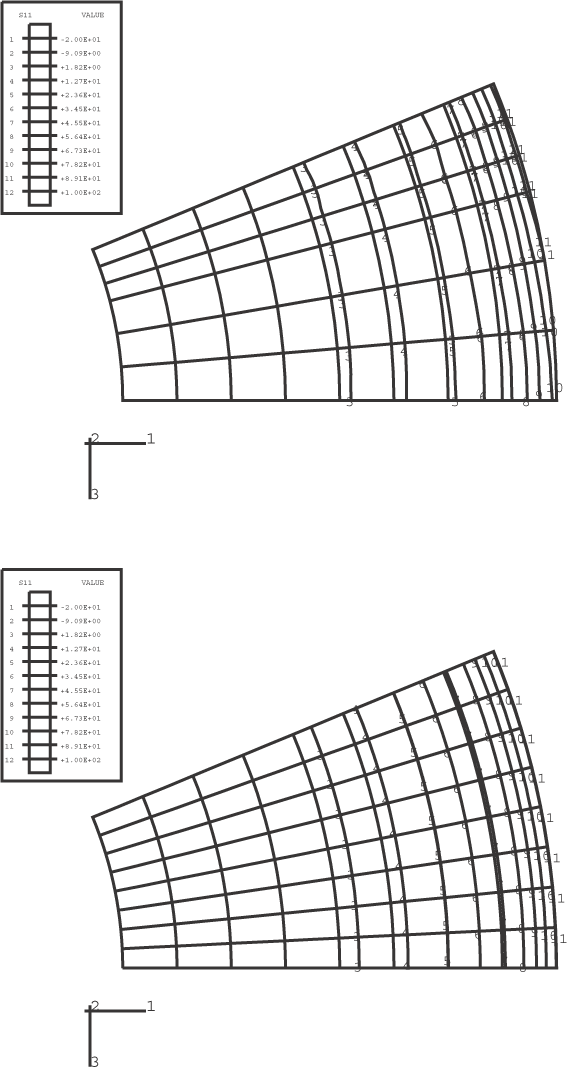
The mesh for the three-dimensional analysis without substructures, shown in Figure 3, represents a 22.5° segment of the pipe joint and employs second-order brick elements with reduced integration, C3D20R, for the pipe hub/flange and bolts. The gasket is modeled with C3D20R elements or GK3D18 elements. The top figure shows the mesh of the pipe hub and flange, and the bottom figure shows both the gasket and bolt (in the lighter color). Contact is modeled by the interaction of contact surfaces defined by grouping specific faces of the elements in the contacting regions. For three-dimensional contact where both the main and secondary surfaces are deformable, the small-sliding contact pair formulation must be used to indicate that small relative sliding occurs between contacting surfaces. No special adjustments need be made for the material properties used in the three-dimensional model because all parts are modeled appropriately.
Four different meshes that use substructures to model the flange are tested. A first-level substructure is created for the entire 22.5° segment of the flange shown in Figure 3, while the gasket and the bolt are meshed as before. The nodes on the flange in contact with the bolt cap form a node-based surface, while the nodes on the flange in contact with the gasket form another node-based surface. These node-based surfaces will form contact pairs with the main surfaces on the bolt cap and on the gasket, which are defined using the surface definition options. The retained degrees of freedom on the substructure include all three degrees of freedom for the nodes in these node-based surfaces as well as for the nodes on the 0° and 22.5° faces of the flange. Appropriate boundary conditions are specified at the substructure usage level.
A second-level substructure of 45° is created by reflecting the first-level substructure with respect to the 22.5° plane. The nodes on the 22.5° face belonging to the reflected substructure are constrained in all three degrees of freedom to the corresponding nodes on the 22.5° face belonging to the original first-level substructure. The half-bolt and the gasket sector corresponding to the reflected substructure are also constructed by reflection. The retained degrees of freedom include all three degrees of freedom of all contact node sets and of the nodes on the 0° and 45° faces of the flange. MPC-type CYCLSYM is used to impose cyclic symmetric boundary conditions on these two faces.
A third-level substructure of 90° is created by reflecting the original 45° second-level substructure with respect to the 45° plane and by connecting it to the original 45° substructure. The remaining part of the gasket and the bolts corresponding to the 45°–90° sector of the model is created by reflection and appropriate constraints. In this case it is not necessary to retain any degrees of freedom on the 0° and 90° faces of the flange because this 90° substructure will not be connected to other substructures and appropriate boundary conditions can be specified at the substructure creation level.
The final substructure model is set up by mirroring the 90° mesh with respect to the symmetry plane of the gasket perpendicular to the y-axis. Thus, an otherwise large analysis ( 750,000 unknowns) when no substructures are used can be solved conveniently ( 80,000 unknowns) by using the third-level substructure twice. The sparse solver is used because it significantly reduces the run time for this model.
Finally, a three-dimensional matrix-based model is created by replacing elements for the entire 22.5° segment of the flange shown in Figure 3 with stiffness matrices, while the gasket and the bolt are meshed as before. Contact between the flange and gasket and the flange and bolt cap is modeled using node-based secondary surfaces just as for the substructure models. Appropriate boundary conditions are applied as in the three-dimensional model without substructures.
