Model description
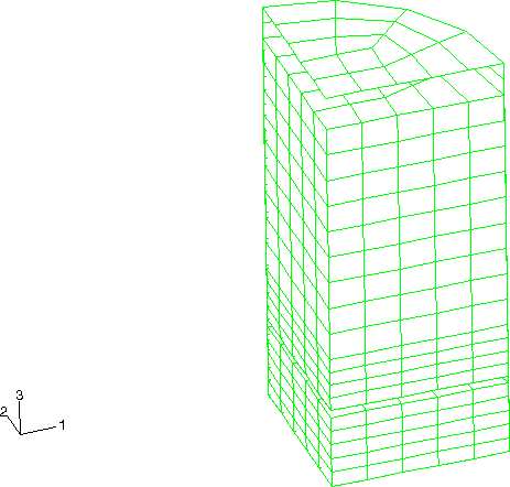
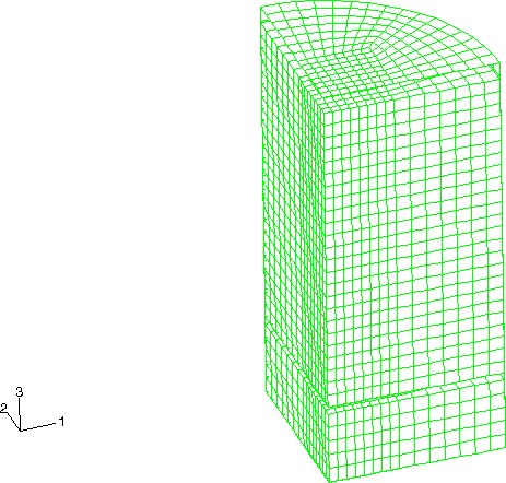
The containment cask shown in Figure 2 consists of two compartments. The upper compartment surrounds the fluid and is made of stainless steel (304L). It has a height of 580 mm (22.8 in), a diameter of 300 mm (11.8 in), and a wall thickness of 4.76 mm (0.187 in). The top mild steel cover has a thickness of 9.52 mm (0.375 in). The water is filled to a depth of 522 mm (20.55 in), which is 90% of the container's capacity. Figure 3 shows the original, coarse mesh of C3D8R elements used to model the fluid. Contact conditions are defined between the fluid and the inside of the upper compartment.
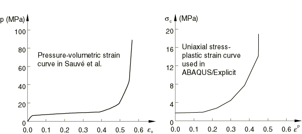
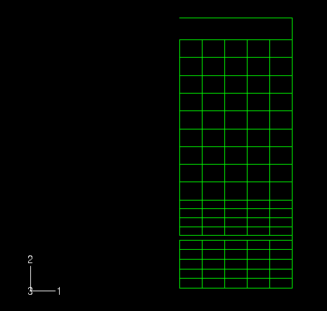
An impact limiter made of polyurethane foam is contained within the bottom mild steel compartment of the cask. The height of the foam impact limiter is 127.3 mm (5.01 in). Figure 4 shows the coarse mesh used to model the foam. Contact conditions are defined between the foam and the inside of the bottom compartment of the cask. The foam impact limiter and the fluid/stainless steel liner are separated by a mild steel bulkhead with a thickness of 12.7 mm (0.5 in). A 12.7 mm (0.5 in) air gap exists between the top of the foam surface and this bulkhead.
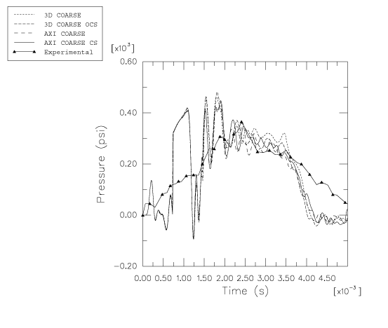
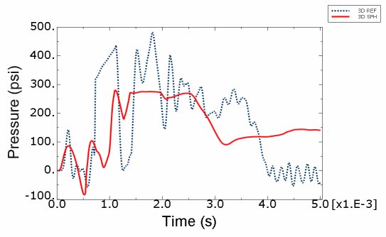
In the experiment a pressure transducer is located in the polyurethane foam on the centerline of the cask at the top of the impact limiter. This result is compared with vertical stress-time histories taken from the element at the top of the foam model on the centerline.
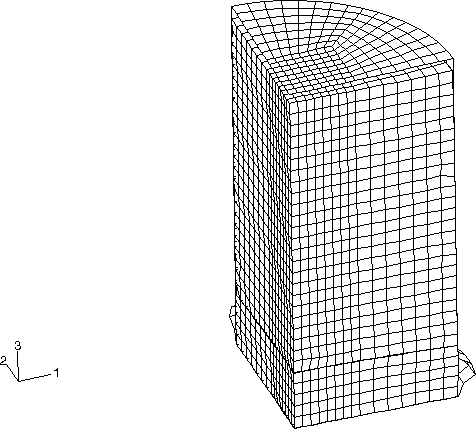
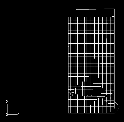
Both axisymmetric and three-dimensional models are analyzed. Figure 5 shows the three-dimensional model formed by assembling the parts shown in Figure 2 through Figure 4. The equivalent axisymmetric model is shown in Figure 6. The corresponding smoothed particle hydrodynamic model incorporates PC3D elements for both the water and the foam parts of the model.
Contact pairs are defined between the solids and the shells. Element-based surfaces are defined on the shells, and node-based surfaces are defined containing the nodes on the outer surfaces of the solid or particle elements. Input files that use the alternative general contact algorithm are also provided. The shell thickness was not taken into account when the original meshes were designed, and the outer surface of the solids usually coincides with the midsurface of the enclosing shell. This would lead to an initial overclosure of one-half the shell thickness, but contact at the midsurface of the shell is enforced, as if the shell had zero thickness. The use of a node-based surface implies a pure main-secondary relationship for the contact pair. This is important in this problem because the default in Abaqus/Explicit when contact is defined between shells and solids is to define a pure main-secondary relationship with the solids as the main and the shells as the secondary. In this case the shell structures are much stiffer than the fluid and foam structures, so the main-secondary roles must be reversed.
For the axisymmetric model two cases using different section controls for the foam and fluid elements are analyzed. The first case uses a linear combination of stiffness and viscous hourglass control; the second case uses the default section controls (the integral viscoelastic form for hourglass control). The three-dimensional model also has two cases with different section controls for the foam and fluid elements. The first case uses the orthogonal kinematic formulation and combined (viscous-stiffness form) hourglass control; the second three-dimensional case uses the default section controls (the average strain kinematic formulation and the integral viscoelastic form for hourglass control). The section controls used are summarized in Table 1. Coarse and refined meshes are used for all analysis cases.
