Confined compression of multiple two-dimensional cylinders with different material properties

This example illustrates the use of general contact in Abaqus/Explicit for a two-dimensional analysis.

This page discusses:

ProductsAbaqus/Explicit

Application description

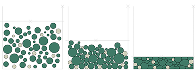
In this example a simple U-shaped container is simulated using rigid elements (R2D2), and it is initially filled with two-dimensional cylinders modeled as plane stress elements (CPS3 and CPS4R). A plane stress state approximates relatively thin bodies, so this model may be representative of short cylinders. The model could be converted to approximating the response for long cylinders by switching to the corresponding plane strain element types (CPE3 and CPE4R).

In the second part of the analysis, the deformable cylinders are highly compressed by a horizontal rigid lid.

Abaqus modeling approaches and simulation techniques

Materials

Two different materials are used in this example. The cylinders colored green in Figure 2 are modeled using a hyperelastic material (polynomial model with N=1; Mooney-Rivlin) with the constants C10=4.48632 MPa, C01=4.48632 MPa, and D1=0.02229 MPa−1, such that the initial shear modulus μ0=2(C10+C01)=17.9452 MPa, and the initial bulk modulus K0=2D1=89.72633 MPa. The density is set to 1.71E–8 tonne/mm3. The cylinders colored white in Figure 2 are linear elastic with Young's modulus of 70,000 MPa, Poisson's ratio of 0.3, and density of 7.8E–8 tonne/mm3. The shear and bulk modulus of the white cylinders are μ=E2(1+υ) =26.923 MPa and K=E3(12υ) =58.333 MPa, respectively; therefore, the white cylinders are three orders of magnitude stiffer than the green cylinders.

Boundary conditions

The rigid container is fully constrained. The rigid lid has a specified displacement in the negative Y-direction equal to –54.0 mm applied using a linear amplitude. The cylinders are free to move in the plane except for contact.

Loads

The entire system is subjected to gravity loading in the Y-direction.

Interactions

Contact is defined using general contact with the option to automatically include the whole exterior surface (see Figure 1). This type of automated contact definition is much simpler than defining a priori all possible contact pairs that may interact during the simulation. The lid and container surfaces are modeled as overlapping to ensure that the contents remain inside the container, and contact exclusions are specified as part of the contact definition to avoid considering contact between the lid and container surfaces during the simulation.

A friction coefficient of 0.1 is used as the default for all contact interactions.

Results and discussion

The cylinders are subjected only to gravity loading in the initial phase of the analysis, such that the cylinders settle on the bottom of the container (see middle image of Figure 2). Next, the rigid lid is moved downward to compress the cylinders (see right side of Figure 2). As expected, due to the large stiffness discrepancy between the two materials, most deformation occurs in the green cylinders, which are made of the softer, hyperelastic material.

Figure 3 shows that, as expected, the reaction force on the reference node of the rigid lid is very small during the first phase of the analysis and increases exponentially as the lid compresses the cylinders.

Due to the high number of increments (> 1 million), the analysis is run in double precision to prevent the accumulation of round-off errors.

Figures

Figure 1. General contact surface definition at the initial configuration.

Figure 2. Compression of the two-dimensional cylinders at different stages of the analysis.

Figure 3. Reaction force in Y-direction of the reference node of the lid.