This example illustrates the forming of a three-dimensional shape
by a deep drawing process.
The following
Abaqus
features are demonstrated:
transferring results from
Abaqus/Explicit
to
Abaqus/Standard
using the import analysis technique;
comparing results from an analysis sequence that uses
Abaqus/Explicit
for a forming step and
Abaqus/Standard
for a springback analysis with results obtained using
Abaqus/Standard
for both the forming and springback steps; and
comparing characteristics of different contact formulations with
finite sliding, especially with regard to the treatment of surface thickness.
In general, the forming procedure involves a forming step followed by a
springback that occurs after the blank is removed from the tool. The goal of
analyzing the forming procedure is to determine the final deformed shape after
springback.
Geometry
The blank is initially square, 200 mm by 200 mm, and is 0.82 mm thick. The
rigid die is a flat surface with a square hole 102.5 mm by 102.5 mm, rounded at
the edges with a radius of 10 mm. The rigid square punch measures 100 mm by 100
mm and is rounded at the edges with the same 10 mm radius. The rigid blank
holder can be considered a flat plate, since the blank never comes close to its
edges. The geometry of these rigid parts is illustrated in
Figure 1.
Materials
The blank is made of aluminum-killed steel, which is assumed to satisfy the
Ramberg-Osgood relation between true stress and logarithmic strain,
with a reference stress value (K) of 513 MPa and a
work-hardening exponent (n) of 0.223. Isotropic elasticity
is assumed, with a Young's modulus of 211 GPa and a Poisson's ratio of 0.3. An
initial yield stress of 91.3 MPa is obtained from these data. The stress-strain
behavior is defined by piecewise linear segments matching the Ramberg-Osgood
curve up to a total (logarithmic) strain level of 107%, with Mises yield,
isotropic hardening, and no rate dependence.
Boundary conditions and loading
Given the symmetry of the problem, it is sufficient to model only a
one-eighth sector of the box. However, for easier visualization we have
employed a one-quarter model. Symmetry boundary conditions are applied at the
quarter edges of the blank. The punch and the blank holders are allowed to move
only in the vertical direction. Allowing vertical motion of the blank holders
accommodates changes in the blank thickness during forming.
Interactions
Contact interaction is considered between the blank and the punch with a
friction coefficient of 0.25 and between the blank and the die with a friction
coefficient of 0.125. The contact interaction between the blank and the blank
holders is assumed to be frictionless.
Abaqus modeling approaches and simulation techniques
The most efficient way to analyze this type of problem is to analyze the
forming step using
Abaqus/Explicit
and to import the results in
Abaqus/Standard
to analyze the springback. For verification purposes the complete analysis is
also carried out with
Abaqus/Standard.
However, this is computationally more expensive and will be prohibitively more
expensive for simulation of the forming of realistic, complex components.
This problem is used in Nagtegaal and Taylor (1991) where implicit and
explicit finite element techniques for forming problems are compared. The
computer time involved in running the simulation using explicit time
integration with a given mesh is directly proportional to the time period of
the event, since the stable time increment size is a function of the mesh size
(length) and the material stiffness. Thus, it is usually desirable to run the
simulation at an artificially high speed compared to the physical process. If
the speed in the simulation is increased too much, the solution does not
correspond to the low-speed physical problem; i.e., inertial effects begin to
dominate. In a typical forming process the punch may move at speeds on the
order of 1 m/sec, which is extremely slow compared to typical wave speeds in
the materials to be formed (the wave speed in steel is approximately 5000
m/sec). In general, inertia forces will not play a dominant role for forming
rates that are considerably higher than the nominal 1 m/sec rates found in the
physical problem. Therefore, explicit solutions are obtained with punch speeds
of 10, 30, and 100 m/sec for comparison with the static solution obtained with
Abaqus/Standard.
In the results presented here, the drawing process is simulated by moving the
reference node for the punch downward through a total distance of 36 mm in
0.0036 seconds. A detailed comparison of analyses of various metal forming
problems using explicit dynamic and static procedures is discussed in the paper
by Nagtegaal and Taylor (1991).
Although this example does not contain rate-dependent material properties,
it is common in sheet metal forming applications for this to be a
consideration. If the material is rate-dependent, the velocities cannot be
artificially increased without affecting the material response. Instead, the
analyst can use the technique of mass scaling to adjust the effective punch
velocity without altering the material properties.
Rolling of thick plates
contains an explanation and an example of the mass scaling technique.
Summary of analysis cases
Forming analysis with
Abaqus/Explicit.
Case 1a
Using the general contact capability.
Case 1b
Using the kinematic contact pairs.
Case 1c
Using penalty contact pairs.
Case 1d
Forming analysis of a fine mesh case using the general contact
capability (included for the sole purpose of testing the performance of the
Abaqus/Explicit
code).
Case 1e
Forming analysis of a fine mesh case using kinematic contact pairs
(included for the sole purpose of testing the performance of the
Abaqus/Explicit
code).
Springback analysis with
Abaqus/Standard.
Case 2a
Abaqus/Standard
springback analysis using an import analysis with no update of the reference
configuration.
Case 2b
Abaqus/Standard
springback analysis using an import analysis with update of the reference
configuration.
Case 2c
Springback analysis of a fine mesh case (included for the sole
purpose of testing the performance of the
Abaqus/Standard
code) using an import analysis with update of the reference configuration.
Forming and springback analysis with
Abaqus/Standard.
Case 3a
Using the surface-to-surface contact
formulation.
Case 3b
Using the node-to-surface contact
formulation.
Analysis types
As described earlier, the import capability in
Abaqus
is utilized to run the forming step as an explicit dynamic analysis followed by
a static stress analysis using
Abaqus/Standard
for calculating the springback. For comparison, results from a complete static
stress analysis using
Abaqus/Standard
for both the forming and the springback steps are presented.
Analysis techniques
The import feature in
Abaqus
is used for transferring results from
Abaqus/Explicit
to
Abaqus/Standard.
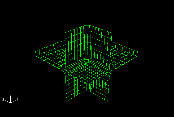
Mesh design
The blank is modeled with 4-node, bilinear finite-strain elements (type S4R); while the punch, die, and the blank holder are meshed using
4-node, three-dimensional rigid surface elements (type R3D4). The mesh design for the various parts is shown in
Figure 1
and
Figure 2.
Loads
The blank is held between the blank holders by applying a concentrated load
of 22.87 kN. Further loading on the blank is applied by contact forces with the
punch in the forming step.
Analysis steps
Using
Abaqus/Explicit
for the forming procedure involves a single forming step where the rigid punch
is pushed against the blank while the blank is held by the blank holders by
applying a concentrated load. This description applies to Cases 1a–1e. For the
import analysis in
Abaqus/Standard
a single step is used to calculate the springback as in Cases 2a–2c. For the
complete analysis in
Abaqus/Standard
as in Cases 3a and 3b, the following steps are adopted:
First step: the blank holders are brought in contact with the blank by
applying a small displacement to the reference point of one of the rigid blank
holders.
Second step: a concentrated load is applied to the reference point of
the blank holder to hold the blank in place while maintaining contact.
Following steps: the forming is effected by pushing the rigid punch
against the blank.
Final two steps: the springback is analyzed by deactivating the
contact pairs.
Output requests
The output variables STH for shell thickness and PEEQ for equivalent plastic strain are specifically requested along
with preselected variables. Further, the history of reaction force and
displacement for the punch is also requested.
Case 1a: Explicit forming analysis using general contact
This analysis pertains only to the forming step. For the complete analysis
the forming step in this case needs to be followed by a springback analysis
(either Case 2a or Case 2b).
Interactions
General contact is used (see the general contact specification) to define
contact interactions in this case. This allows very simple definitions of
contact with very few restrictions on the types of surfaces involved (see
About General Contact in Abaqus/Explicit).
However, general contact does not account for changes in shell thickness by
default. Consequently, the general contact surface property assignment must
account for thinning of the blank.
Case 1b: Explicit forming analysis using kinematic contact pairs
This analysis again pertains only to the forming step. For the complete
analysis the forming step needs to be followed by a springback analysis (either
Case 2a or Case 2b).
Interactions
Contact pairs are defined to include blank interaction with the punch, die,
and the blank holder separately with appropriate friction behavior as
previously specified. The contact pair algorithm, which is specified in the
contact pair definition, has more restrictions on the types of surfaces
involved and often requires more careful definition of contact (see
About Contact Pairs in Abaqus/Explicit).
Contact interactions are defined between all element-based surfaces in the
model.
Case 1c: Explicit forming analysis using penalty contact pairs
This analysis pertains only to the forming step. The springback calculations
have to be done separately (Case 2a or Case 2b).
Interactions
Penalty contact is specified for contact pairs to include blank interaction
with the punch, die, and the blank holder separately with appropriate friction
behavior.
Case 1d: Explicit forming analysis using general contact with a refined
mesh
In this case the mesh for the blank is uniformly refined so that the number
of elements in each direction is twice the number in the previous cases. This
case is run to purely benchmark the efficiency of performing an explicit
analysis.
Interactions
The contact interactions are exactly the same as in Case 1a.
Case 1e: Explicit forming analysis using kinematic contact pairs with a
refined mesh
In this case the refined mesh defined in Case 1d is utilized for performing
the explicit forming analysis.
Interactions
The contact interactions are exactly the same as in Case 1b.
Case 2a: Static springback analysis with no update of the reference
configuration during import
For running this case, a prior explicit forming analysis (Case 1a, Case 1b,
or Case 1c) should have been completed for importing results into
Abaqus/Standard.
By specifying an import analysis with no update of the reference configuration,
the displacements are the total values relative to the original reference
configuration before the forming analysis. This makes it easy to compare the
results with the analysis in which both the forming and springback are analyzed
with
Abaqus/Standard.
Boundary conditions
Boundary conditions are imposed in the
Abaqus/Standard
analysis to prevent rigid body motion and for symmetry. The node at the center
of the box is fixed in the z-direction.
Interactions
No contact interactions are used in this analysis once the deformed sheet
with its material state at the end of
Abaqus/Explicit
is imported.
Case 2b: Static springback analysis with update of the reference
configuration during import
Similar to Case 2a, a prior explicit forming analysis (Case 1a, Case 1b, or
Case 1c) should have been completed for importing results into
Abaqus/Standard.
However, specifying an import analysis with update of the reference
configuration implies that the displacements are relative to the deformed
configuration at the end of the forming analysis. The boundary conditions and
interactions are exactly the same as Case 2a.
Case 2c: Static springback analysis using a refined mesh with update of
the reference configuration during import
For running this case, Case 1d or Case 1e for explicit forming analysis
should have been completed for importing results into
Abaqus/Standard.
Here again, specifying an import analysis with update of the reference
configuration implies that the displacements are relative to the deformed
configuration at the end of the forming analysis. The boundary conditions and
interactions are exactly the same as Case 2a.
Case 3a: Static analysis of forming and springback using
surface-to-surface contact
In this analysis both the forming and the springback steps are analyzed in
Abaqus/Standard.
Interactions
In this case the surface-to-surface contact formulation is invoked. Since
double-sided surfaces are not available in
Abaqus/Standard,
two single-sided surfaces are used to model the blank when the forming step is
modeled in
Abaqus/Standard:
one surface to model the top of the blank and one to model the bottom of the
blank. The surface-to-surface contact formulation considers the original shell
thickness by default throughout the analysis. There is no option to consider
the current shell thickness instead of the original shell thickness.
Solution controls
Contact stabilization is used to avoid chattering between the blank and the
rigid surfaces it is in contact with. In addition, the adaptive automatic
stabilization scheme is applied to improve the robustness of the static
analysis.
Case 3b: Static analysis of forming and springback using node-to-surface
contact
As in Case 3a, both the forming and the springback steps are analyzed in
Abaqus/Standard.
Interactions
In this case the node-to-surface contact formulation is used. Since, shell
thickness cannot be considered by node-to-surface finite-sliding contact,
“softened” contact is used to approximate the thickness (see the modified
contact pressure-overclosure relationship).
Discussion of results and comparison of cases
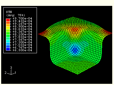
Figure 3,
Figure 5,
and
Figure 4
show contours of shell thickness in the blank at the end of the forming step
before springback in
Abaqus/Explicit
(Case 1a) and
Abaqus/Standard
analyses (Case 3a and Case 3b), respectively.
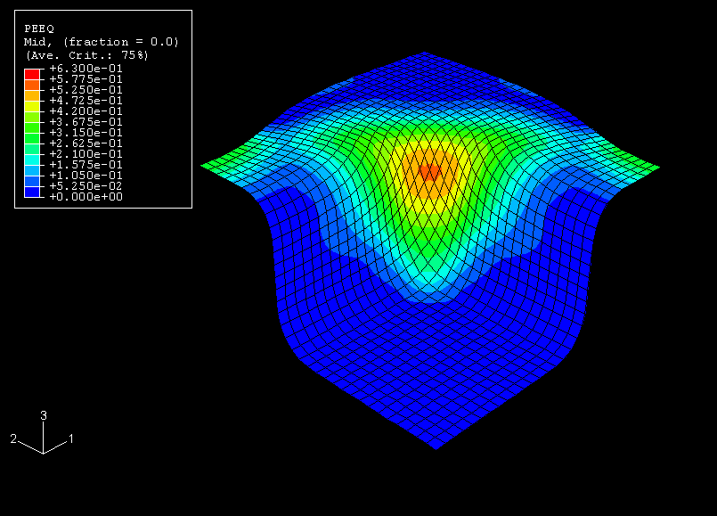
Figure 6,
Figure 7,
and
Figure 8
show contours of equivalent plastic strain in the blank in the final deformed
shape for the
Abaqus/Explicit
and the two
Abaqus/Standard
analyses, respectively. The predicted results are very similar. The
Abaqus/Explicit
results match the surface-to-surface contact formulation in
Abaqus/Standard
more closely than the node-to-surface results in
Abaqus/Standard.
This observation is true for both the equivalent plastic strain contours and
shell thickness contours and is a consequence of the intrinsic differences
between the various contact formulations. The node-to-surface formulation in
Abaqus/Standard
accounts for the shell thickness indirectly by using carefully specified
pressure-overclosure relationships (soft contact). The other analyses use
contact formulations that account for shell thickness directly. Despite the
fact that the surface-to-surface formulation in
Abaqus/Standard
uses the original shell thickness throughout the analysis, the results
correlate well.
Closer inspection of the results reveals that the corners of the box are
formed by stretching, whereas the sides are formed by drawing action. This
effect leads to the formation of shear bands that run diagonally across the
sides of the box, resulting in a nonhomogeneous wall thickness. The material
draws unevenly from the originally straight sides of the blank. Applying a more
localized restraint near the midedges of the box (for example, by applying
drawbeads) and relaxing the restraint near the corners of the box is expected
to increase the quality of the formed product.
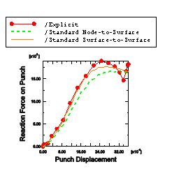
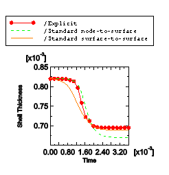
Figure 9 shows the reaction force on the punch, and Figure 10 shows the thinning of an element at the corner of the box. Here again, the results from
the surface-to-surface formulation in Abaqus/Standard match those from Abaqus/Explicit better than the node-to-surface contact formulation in Abaqus/Standard. Despite the approximate treatment of surface thickness via the pressure-overclosure
relationship for the node-to-surface formulation, the shell thicknesses predicted by Abaqus/Explicit and the node-to-surface formulation in Abaqus/Standard differ only by about 4%, reflecting the overall quality of the results.
The springback analysis runs in 6 increments for both of the contact
formulations in
Abaqus/Standard.
Most of the springback occurs in the z-direction,
and the springback is not significant. The corner of the outside edge of the
formed box drops approximately 0.35 mm, while the vertical side of the box
rises by approximately 0.26 mm.
Figure 11
shows a contour plot of the displacements in the
z-direction obtained from the springback analysis
using the node-to-surface formulation.
The analysis with no reference configuration update yields similar results.
However, in this case the displacements are interpreted as total values
relative to the original configuration.
Files
Case 1a: Explicit forming analysis using general contact
Nagtegaal J. C. and L. M.
Taylor, “Comparison of Implicit and Explicit Finite
Element Methods for Analysis of Sheet Forming
Problems,”VDI Berichte No.
894, 1991.
Figures
Figure 1. Meshes for the die, punch, and blank holder. Figure 2. Undeformed mesh for the blank. Figure 3. Contours of shell thickness with
Abaqus/Explicit. Figure 4. Contours of shell thickness with
Abaqus/Standard
using surface-to-surface contact formulation. Figure 5. Contours of shell thickness with
Abaqus/Standard
using node-to-surface contact formulation. Figure 6. Contours of equivalent plastic strain with
Abaqus/Explicit. Figure 7. Contours of equivalent plastic strain with
Abaqus/Standard
using surface-to-surface contact formulation. Figure 8. Contours of equivalent plastic strain with
Abaqus/Standard
using node-to-surface contact formulation. Figure 9. Reaction force on the punch versus punch displacement. Figure 10. Shell thickness of the thinnest part of the blank versus time. Figure 11. Contour plot showing the springback in the
z-direction.