Geometry and materials
The problem discussed here is a model of a pick-up truck (1994 Chevrolet C1500). The model geometry, element connectivity, and material properties are obtained from the Public Finite Element Model Archive of the National Crash Analysis Center at George Washington University. The materials used are described in Inertia relief in a pick-up truck.
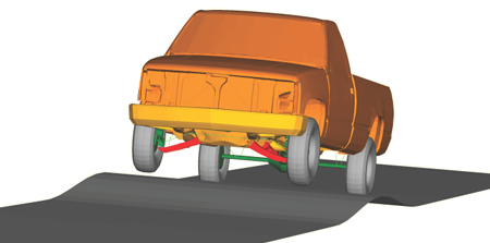
The model is organized as a collection of individual parts connected together. Most parts that undergo only small deformations in addition to a large rigid body motion are defined as display bodies; their deformation can be neglected since only the overall motion of the vehicle is of interest. A display body is created for each of the following parts: the chassis, each of the four A-arms of the front suspension, each of the four wheels, the rear axle, the driveshaft, the engine/transmission, the cabin, each of the two doors, the hood, the seat, the front bumper, the truck bed, and the fuel tank.
The number of attachment points for each display body is determined by its connection points with neighboring parts. The display bodies of the front-wheel assembly are shown connected at attachment nodes in Figure 1.
Several parts deform nonlinearly and are modeled using regular elements. For example, the leaf springs in the rear and the stabilizer bar in the front are modeled with beam elements.
To create the display bodies with appropriate attachment points and realistic material properties, the following steps are taken:
A datacheck analysis is run on every part with deformable elements to determine its mass, rotary inertia, and center of mass.
An instance of this part is used to create a display body.
A reference node created at the center of mass for this part is also used as the reference node for the corresponding display body.
A mass element and a rotary inertia element are created at the reference node.
The reference node is then connected to the attachment points of the part using either BEAM or CARTESIAN and CARDAN connectors with stiff elastic properties.
The connections between the attachment points of two display bodies are modeled using connector elements. JOIN and REVOLUTE connectors are used to model the hinges between each of the following parts: the A-arms and chassis, the doors and cabin, the hood and cabin, the wheels and knuckles, and the leaf springs and chassis. CARTESIAN and CARDAN connections with connector elasticity, connector damping, and connector friction behaviors are used to define some of the bushing connections (e.g., the engine mounts). Two UNIVERSAL connectors are used to model the driveshaft connections to the transmission in the front and to the differential in the back. BEAM connectors are used to model rigid connections between parts. In cases where the BEAM connectors form a closed loop, the model becomes overconstrained. In such situations CARTESIAN and CARDAN connectors with elasticity are used instead of some of the BEAM connectors. A connector motion is applied to an AXIAL connector to lock (or open) the doors and the hood. For steering the vehicle, a connector motion is applied to a SLOT connector and is used to specify the steering for the steering rack. The struts are modeled using an AXIAL connection by specifying approximate nonlinear elasticity and damping.
The radial forces in the tires are modeled approximately using a simplified CALSPAN tire model (Frik, Leister, and Schwartz, 1993) implemented via user subroutine UEL. A radial stiffness of 600 N/mm is considered. Friction is not accounted for in this user subroutine.