Problem description
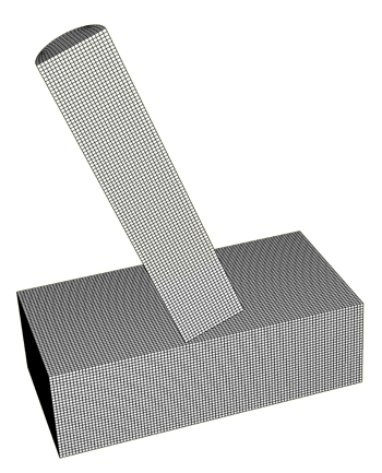
The undeformed mesh is shown in Figure 1. The armor plate has a thickness of 3 mm. A relatively small rectangular region of the plate is modeled for simplicity, with fully fixed boundary conditions specified on three cutting planes and y-axis symmetry specified on one cutting plane. The projectile, which is 10 mm in length and has a radius of 1 mm, has an initial speed of 2000 m/sec. The cylindrical axis of the projectile is 20° from perpendicular to the plate, and the initial velocity of the projectile is aligned with its cylindrical axis. Half of the projectile is modeled, with y-axis symmetry specified on the cutting plane. The plate and projectile material properties are identical, with Young's modulus of 210 GPa, Poisson's ratio of 0.3, and density of 7800 kg/m3. The yield stress of the material is specified as a function of the equivalent plastic strain at different equivalent plastic strain rates. The material definition also includes failure models with progressive damage, which causes Abaqus/Explicit to remove elements from the mesh as they fail. Both the ductile and shear initiation criteria are used: the ductile criterion is specified in terms of the plastic strain at the onset of damage as a tabular function of the stress triaxiality; the shear criterion is specified in terms of the plastic strain at the onset of damage as a tabular function of the shear stress ratio. The damage evolution energy is assumed to be 500 N/m.
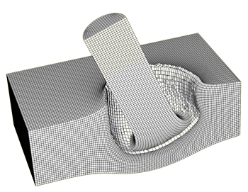
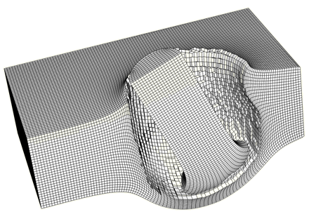
During the analysis elements from both bodies are deleted due to material failure, which calls for the use of element-based surfaces that can adapt to the newly exposed surfaces of the remaining active elements. The general contact algorithm supports element-based surfaces that evolve in this manner (whereas the contact pair algorithm does not) with two distinct approaches. In the first approach all surface faces that may become exposed during the analysis, including faces that are originally in the interior of bodies, must be included at the beginning of the analysis. Only the interior faces that are expected to participate in contact are included in the contact domain in this analysis to minimize the memory use (including interior faces for all elements in the model would more than double the memory use). In the second approach the surface faces are generated and activated dynamically only when interior elements are exposed. This results in a possible memory savings compared to the first approach.
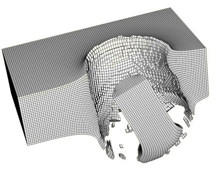
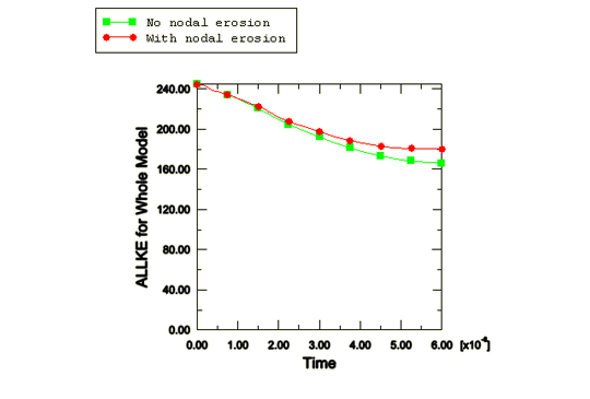
By default, the general contact algorithm does not include nodal erosion, so contact nodes will still take part in the contact calculations even after all of the surrounding elements have failed. These nodes act as free-floating point masses that can experience contact with the active contact faces. For comparison purposes, the analysis is also conducted including nodal erosion, which causes the nodes to be removed from the contact calculations once all surrounding elements have failed (and can result in computational savings). The momentum transfer associated with free-flying nodes is expected to be significant in this example, so nodal erosion is not recommended.
A plane strain version of the model is also included to demonstrate contact with eroding bodies for a two-dimensional simulation. Consistent boundary conditions, initial conditions, in-plane dimensions, and material properties are used for this model and the three-dimensional model. Other geometric characteristics are inconsistent between the two-dimensional and three-dimensional models, so results are expected to differ.