Application description
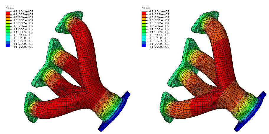
Heat transfer in engine exhaust manifolds is governed by three effects: conduction through the metal, convection from the hot exhaust gases, and radiative exchange between different parts of the metal surface. This example illustrates the computation of the equilibrium thermal state of a manifold subject to these effects. The units of length in this example are millimeters; otherwise, standard metric units are used.
The procedure consists of a single heat transfer step in which the thermal loading conditions are ramped up from zero. The boundary constraints on the manifold flanges are a simplification of those experienced under operating conditions: the temperatures at the cylinder head and the outlet are fixed. Convection due to heat transfer from the hot exhaust is applied at the internal surfaces of the manifold tubes. Radiation is modeled between the internal surfaces of the tubes using several methods: the cavity radiation method, with and without cavity parallel decomposition enabled, and using average-temperature radiation conditions.
Geometry
The exhaust manifold part being analyzed is depicted in Figure 1. It consists of a four tube exhaust manifold with three flanges, as in Exhaust manifold assemblage.
Materials
The manifold is cast from gray iron with a thermal conductivity of 4.5× 10⁻² W/mm/°C, a density of 7800 × 10−9 kg/mm3, and a specific heat of 460 J/kg/°C. The manifold begins the analysis with an initial temperature of 20°C. The part is dimensioned in millimeters, and the temperature is measured in °C, so the Stefan Boltzmann constant is taken as 5.669 × 10⁻¹⁴ W/mm2/K4 and absolute zero is set at 273.15°C below zero. The surface emissivity of gray iron is taken as a constant value of 0.77.
Initial conditions
The initial temperature of the manifold is set to 20°C.
Boundary conditions and loading
The hot exhaust gases create a heat flux applied to the interior tube surfaces. In this example this effect is modeled using a surface-based film condition, with a constant temperature of 816°C and a film condition of 500 × 10−6 W/mm2/°C. A temperature boundary condition of 355°C is applied at the flange surfaces attached to the cylinder head, and a temperature boundary condition of 122°C is applied at the flange surfaces attached to the exhaust.


