Geometry and material
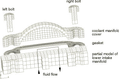
The portion of the lower intake manifold that is modeled has two passages. Coolant flows from one passage into the manifold cover and back out through the other passage. Two steel bolts secure the cover to the manifold. The bolt shanks have a diameter of 6.0 mm, and the bolt heads have a diameter of 11.8 mm. The bolts and the lower intake manifold are assigned a Young's modulus of 2.0 × 10⁵ MPa, a Poisson's ratio of 0.28, and a coefficient of thermal expansion of 1.6 × 10⁻⁵ per °C. The aluminum coolant manifold cover has a Young's modulus of 7.1 × 10⁴ MPa, a Poisson's ratio of 0.33, and a coefficient of thermal expansion of 2.3 × 10⁻⁵ per °C.
The metal components (bolts, cover, and intake manifold) are modeled with three-dimensional continuum elements: 1304 first-order brick elements with incompatible deformation modes (C3D8I) and 208 first-order prism elements (C3D6). The C3D8I elements are chosen to capture the bending of the cover, using only one element through its thickness. The C3D6 elements are used only where geometric constraints preclude the use of C3D8I elements.
The gasket schematic shown in Figure 2 has two distinct regions. The majority of the gasket is composed of a 0.79 mm thick, flat, crushable paper foam material. To ensure proper sealing pressures for this joint, a 0.076 mm thick silicone bead has been silkscreened along the top surface of the gasket encircling the interior cavity. Placing silicone beads on gaskets results in a change in the load transmitting characteristics of the gasket, which often improves both the recovery properties of the gasket and its potential to remain sealed for the long term.
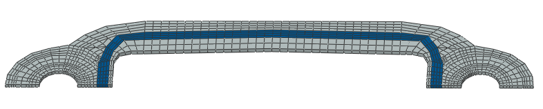
The entire gasket, including the bead, is modeled as a flat sheet with one gasket element through the thickness (see Figure 3). A relatively fine mesh is used for the gasket to capture the in-plane variation of the gasket sealing pressure. This creates a mismatched mesh across the contacting surfaces, but Abaqus contact definitions do not require one-to-one matching meshes across contact pairs. The gasket components (silicone bead region and paper foam region) are modeled with 973 first-order 8-node area elements (GK3D8) and 29 first-order 6-node area elements (GK3D6). The physical thickness of the entire sheet of gasket elements corresponds to the initial combined height of the paper foam and the silicone bead, 0.866 mm. The elements in the region of the gasket beneath the silicone bead are assigned different gasket properties from the rest of the elements in the gasket model. The paper foam region is initially not in contact with the cover. The initial gap is 0.076 mm. No pressure is generated in this portion of the gasket until the gap has closed. Gasket region property distinctions, such as initial gaps and different pressure versus closure relationships, are assigned to corresponding element sets by referring to different gasket behavior definitions.
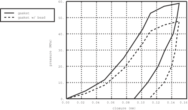
Experimentally determined pressure versus closure curves for the two distinct gasket regions without the initial gap taken into account are shown in Figure 4. Tabular representations of these curves are specified using a gasket thickness-direction behavior that is associated with the respective gasket behavior definitions. Creep/relaxation properties of the gasket and temperature-dependent pressure versus closure properties, capturing such effects as the glassy transition temperature of the silicone bead, are not accounted for in this example. Initially, Abaqus considers the gasket behavior to be nonlinear elastic, such that loading and unloading occur along the same user-defined nonlinear path. Abaqus considers yielding to occur once the slope of the pressure versus closure curve decreases by at least 10%. In addition to the single loading curve, whose closure increases monotonically, the user can define any number of unloading curves at different levels of plastic closure. Yielding occurs at a closure of 0.1118 mm for both regions of the gasket in this example, after which the gasket stiffness decreases slightly up to a closure of 0.15 mm, the final point on the loading curve. Beyond the data of the loading curve defined by the user, Abaqus considers the gasket to behave with a fully crushed elastic response by linearly extrapolating the last segment of the last specified unloading curve (alternatively, the user could have specified a piecewise linear form).
A single unloading curve is defined for each of the two gasket regions: the unloading curve for the silicone bead region is defined at 0.11 mm of plastic closure, and the unloading curve for the paper foam region is defined at 0.09 mm of plastic closure. Any unloading of the gasket beyond the yield point occurs along a curve interpolated between the two bounding unloading curves, which—for this example—are the initial, nonlinear elastic curve and the single unloading curve.
Gasket materials often have higher coefficients of thermal expansion than most of the metals from which the bolts and flanges are made. For situations involving wide and rapid temperature fluctuations resultant differences in relative expansion and contraction can have a significant effect on the sealing properties of the gasket. The coefficient of thermal expansion for the silicone bead region is 1.2 × 10⁻⁴ per °C, and for the paper foam region it is 3.0 × 10⁻⁵ per °C.
In this case, because of the differences in thermal expansion between the aluminum cover and the steel intake manifold, it is important to account for the membrane and transverse shear properties of the gasket and to model frictional effects between mating surfaces. For this analysis the silicone bead region of the gasket is defined to have a membrane stiffness of 75 MPa and a transverse shear stiffness of 40 MPa. The base foam material is defined with a value of 105 MPa for the membrane stiffness and a value of 55 MPa for the transverse shear stiffness. A friction coefficient of 0.2 is used between all mating surfaces.
A separate analysis is included in this example problem using the “thickness-direction only” version of the gasket elements (GK3D8N and GK3D6N). These elements respond only in the thickness direction and have no membrane or transverse shear stiffness properties. They possess only one degree of freedom per node. As a result, frictional effects cannot be included at the surfaces of these elements. They are more economical than more general gasket elements that include membrane and transverse shear responses and may, thus, be preferable in models where lateral response can be considered negligible.