Side curtain airbag analysis using the lumped kinetic molecular method

This example illustrates the use of the lumped kinetic molecular method in an automotive airbag deployment analysis.

This example demonstrates the following features and techniques:

  • using an LKM-type pressure-overclosure contact interaction,
  • using the particle generator to work as the airbag inflator,
  • using PD3D elements to model lumped gas molecules, and
  • switching from the LKM method to the uniform pressure method during the analysis.

This page discusses:

ProductsAbaqus/Explicit

Application description

Geometry

The side curtain airbag model is based on the airbag model described in Side curtain airbag impactor test. The geometry of the airbag and the rigid head form are the same as described in that example problem. The inflator gas is modeled using the lumped kinetic molecular (LKM) method. Because the LKM method is able to capture the nonuniformity of pressure in the airbag, only a single fluid cavity spanning the entire airbag is used.

Abaqus modeling approaches and simulation techniques

Mesh design

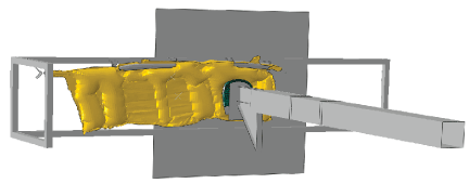
The airbag is discretized using 3-node M3D3 membrane elements. A single fluid cavity is associated with the airbag. In contrast to the model used in Side curtain airbag impactor test (where three inflators are used to inject gas into three different chambers of the airbag) a single particle generator is used to model the inflator device; it injects gas into the single fluid cavity associated with the airbag. The inlet of the particle generator consists of a single rectangular facet. The inlet facet is located at one end of a rigid fill tube and generates the gas particles inside the tube. The rigid inlet and fill tube are meshed with SFM3D4R surface elements. The gas particles generated inside the fill tube enter the airbag through three openings, shown in Figure 1. The placement of the three openings in the fill tube is based on the mid-location of the three chambers into which the three inflators in Side curtain airbag impactor test inject the gas.This example uses 200,000 PD3D discrete elements.

Materials

In Side curtain airbag impactor test six gases are injected by the inflators. Because the molar fractions for the six gases are nearly constant during the analysis, a single equivalent gas is used in this model to replace the six gases. The molecular weight of the equivalent gas is obtained from the molecular weights and molar fractions of the six gases used in Side curtain airbag impactor test. The molecular weight of the equivalent gas is 3.6614e–05 tonnes/mol. The polynomial forms of the constant-pressure molar heat capacity for each individual gas are evaluated at various temperatures. The evaluated values are combined using the mass fractions of individual gases to compute a tabular form of the constant-pressure heat capacity of the equivalent gas. The mass flow rate for the single gas species generated by the particle generator is obtained by combining the mass flow rate data for the three inflators used in Side curtain airbag impactor test. The airbag, as well as the rigid impactor mesh and material, are the same as described in Side curtain airbag impactor test.

Initial conditions

The unstressed reference configuration of the airbag is the same as in Side curtain airbag impactor test. Because there is no direct way to model the initial gas in the lumped kinetic molecular method, the particle generator generates the initial mass of gas at the initial temperature into the airbag over a very short duration of time at the start of the analysis.

Loads

An ambient pressure of 0.101329 MPa is considered outside the airbag. Gravity loading is applied to the model.

Interactions

An LKM-type pressure-overclosure contact interaction is defined between the gas particles, as well as between the gas particles and the airbag.

Solution controls

The discrete section associated with the lumped gas particles refers to a section control that establishes a bounding box within which all gas particle interactions occur. Particles that reach this bounding box are deactivated.

At 25 milliseconds, the lumped kinetic molecular method is deactivated and the uniform pressure method (UPM) is activated. The LKM method is used in the early deployment phase to capture the nonuniform nature of the pressure within the bag. In the later phase of deployment, the airbag is near full inflation, and the pressure is relatively uniform. Switching from the LKM method to UPM reduces the computational expense and allows for modeling of the inflator gas leaking to the environment via vents or permeable fabric and seams. Once the switch occurs, all the gas particles are deactivated.

Output requests

The filtered displacement, velocity, and acceleration of the head form in the vertical direction are requested. The history of the generated mass of gas (PDMASS), average gas temperature (PDTEMP), and average gas pressure (PDPAVG) is obtained via an integrated output request for the entire element set of gas particles. These three output variables are valid until deactivation of the lumped kinetic molecular method. After the activation of the uniform pressure method, output variables CMASS, CTEMP, and PCAV must be used for the generated gas mass, temperature, and pressure, respectively. Output variable CVOL is requested for history of the airbag volume.

Results and discussion

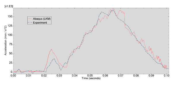
The analysis is performed in domain parallel mode using double precision. Figure 2, Figure 3, and Figure 4 show the deformed shape of the airbag at different stages of deployment. Figure 5, Figure 6, and Figure 7 show the results from the Abaqus/Explicit analysis (displacement, velocity, and acceleration of the head form), along with experimental results. These plots demonstrate the close correlation between the Abaqus/Explicit simulation results and the physical test results.

References

  • Simulation of Airbag Deployment Using the Coupled Eulerian-Lagrangian Method in Abaqus/Explicit. Abaqus Technology Brief, June 2011.

Figures

Figure 1. Particle generator inlet and fill tube with openings.

Figure 2. Deformed configuration at 8.75 ms.

Figure 3. Deformed configuration at 16.25 ms.

Figure 4. Deformed configuration at 80 ms.

Figure 5. Impactor displacement.

Figure 6. Impactor velocity.

Figure 7. Impactor filtered acceleration.