*SUBSTRUCTURE PROPERTY | |||||||
|
| ||||||
ProductsAbaqus/Standard
TypeModel data
LevelThis option is not supported in a model defined in terms of an assembly of part instances.
Required parameters
- ELSET
-
Set this parameter equal to the name of the element set containing the substructures for which properties are being defined.
Optional parameters
- FREQUENCY BASED
-
This parameter is relevant to frequency-based substructures. Frequency-based substructures are used only in a direct steady-state dynamic analysis (see Direct-Solution Steady-State Dynamic Analysis). All other analyses use conventional substructures regardless of the availability of frequency-based substructures.
Set FREQUENCY BASED=ALL FREQUENCIES to use the frequency-based substructure at all frequency points of interest. If the frequency-based substructure is not available at a certain frequency, an operator-averaging-based approximate solution is given at that frequency. If a frequency of interest is beyond the range of frequencies at which the frequency-based substructure is constructed at generation, Abaqus issues an error.
Set FREQUENCY BASED=NO FREQUENCIES to disable the use of the frequency-based substructure at any frequency. The conventional substructure is used instead at all frequencies.
Set FREQUENCY BASED=MATCHED FREQUENCIES (default) to use the frequency-based substructure only at frequencies at which the frequency-based substructure is constructed at generation. At all nonmatching frequencies, the conventional substructure is used.
- POSITION TOL
-
Set this parameter equal to the tolerance on the distance between usage level nodes and the corresponding substructure nodes. If this parameter is omitted, the default is a tolerance of 10−4 times the largest overall dimension within the substructure. If the parameter is given with a value of 0.0, the position of the retained nodes is not checked.
Data line to translate a substructure
- First (and only) line
Value of the translation to be applied in the global X-direction.
Value of the translation to be applied in the global Y-direction.
Value of the translation to be applied in the global Z-direction.
Data lines to translate and/or rotate a substructure
- First line
Value of the translation to be applied in the global X-direction.
Value of the translation to be applied in the global Y-direction.
Value of the translation to be applied in the global Z-direction.
Enter values of zero to apply a pure rotation.
- Second line
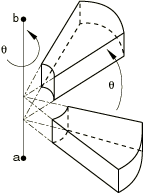
Global X-coordinate of point a on the axis of rotation (see Figure 1).
Global Y-coordinate of point a on the axis of rotation.
Global Z-coordinate of point a on the axis of rotation.
Global X-coordinate of point b on the axis of rotation.
Global Y-coordinate of point b on the axis of rotation.
Global Z-coordinate of point b on the axis of rotation.
Angle of rotation about the axis a–b, in degrees.
Data lines to translate and/or reflect a substructure
- First line
Value of the translation to be applied in the global X-direction.
Value of the translation to be applied in the global Y-direction.
Value of the translation to be applied in the global Z-direction.
Enter values of zero to apply a pure reflection.
- Second line
Enter a blank line.
- Third line
Global X-coordinate of point a in the plane of reflection (see Figure 2).
Global Y-coordinate of point a in the plane of reflection.
Global Z-coordinate of point a in the plane of reflection.
Global X-coordinate of point b in the plane of reflection.
Global Y-coordinate of point b in the plane of reflection.
Global Z-coordinate of point b in the plane of reflection.
- Fourth line
Global X-coordinate of point c in the plane of reflection.
Global Y-coordinate of point c in the plane of reflection.
Global Z-coordinate of point c in the plane of reflection.
Data lines to translate, rotate, and reflect a substructure
- First line
Value of the translation to be applied in the global X-direction.
Value of the translation to be applied in the global Y-direction.
Value of the translation to be applied in the global Z-direction.
- Second line
Global X-coordinate of point a on the axis of rotation (see Figure 1).
Global Y-coordinate of point a on the axis of rotation.
Global Z-coordinate of point a on the axis of rotation.
Global X-coordinate of point b on the axis of rotation.
Global Y-coordinate of point b on the axis of rotation.
Global Z-coordinate of point b on the axis of rotation.
Angle of rotation about the axis a–b, in degrees.
- Third line
Global X-coordinate of point a in the plane of reflection (see Figure 2).
Global Y-coordinate of point a in the plane of reflection.
Global Z-coordinate of point a in the plane of reflection.
Global X-coordinate of point b in the plane of reflection.
Global Y-coordinate of point b in the plane of reflection.
Global Z-coordinate of point b in the plane of reflection.
- Fourth line
Global X-coordinate of point c in the plane of reflection.
Global Y-coordinate of point c in the plane of reflection.
Global Z-coordinate of point c in the plane of reflection.