Elements tested
C3D8R S4R
ProductsAbaqus/Explicit Elements testedC3D8R S4R Features testedAnisotropic friction for general contact in Abaqus/Explicit. Problem description The models consist of a solid element pressed against a shell element,
converted to a rigid element for convenience, and displaced along the shell
surface in varying directions. At the beginning of the analysis both contact
surfaces have a directional preference oriented with the major axis of the
scaling ellipse pointing in the Y-direction (see the
vector plot of CORIENT1 in
Figure 1).
The frictional directional preference factor,
for both surfaces is equal to 0.5. The nominal or average friction coefficient,
is 0.2.
Model:Model-1:
Model-2:
After the shell is rotated, the two surfaces have orthogonal directional preferences and the equivalent scaling ellipse becomes a circle. Material:
Anisotropic behavior:The scaling ellipses can be mathematically treated as tensors. The form in the principal coordinate system is The form in a rotated coordinate system is Each ellipse is defined as The two surface scaling tensors (ellipses) are averaged to determine the contact scaling tensor (ellipse): Initially the major axis of the two ellipses are aligned, and using a balanced weighting method, the contact scaling ellipse becomes The limit shear force in the principal direction is computed by multiplying by the average friction coefficient and the normal force, Results and discussionThe reaction forces are checked and compared with the analytical results.
Input files
Figures  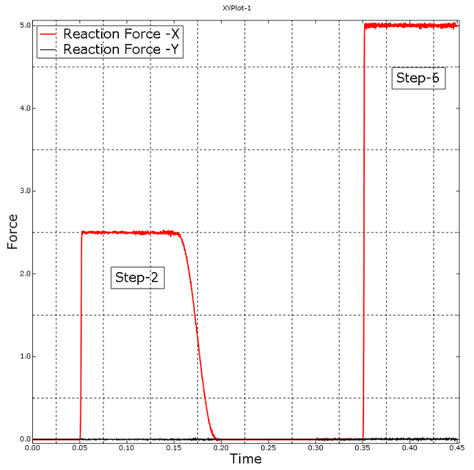 | |||||||||||||||||||||||||||||||||||||
