Elements tested
B21
B22
B31
B32
PIPE21
PIPE31
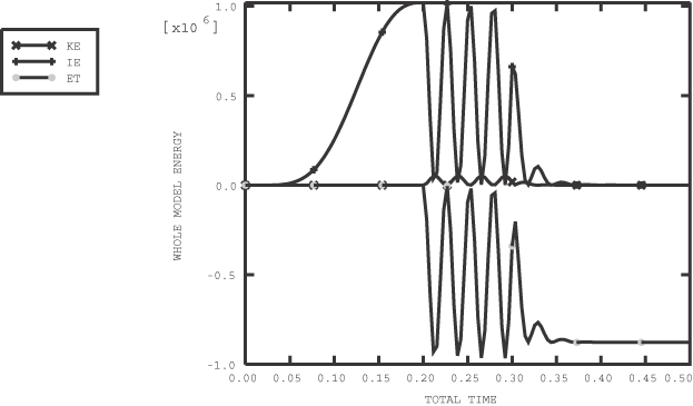
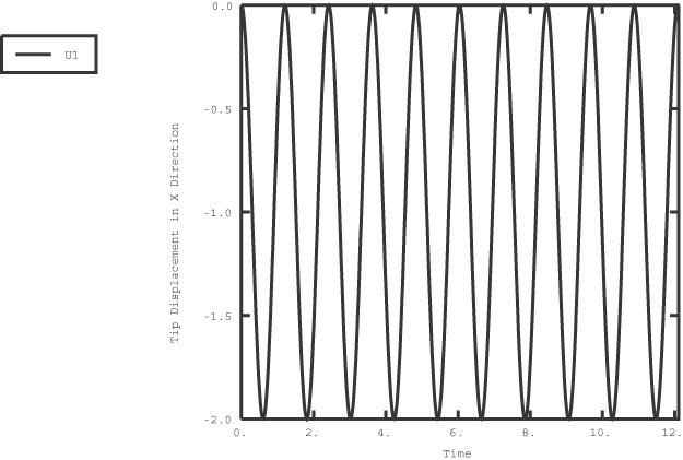
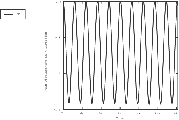
ProductsAbaqus/Explicit Elements testedB21 B22 B31 B32 PIPE21 PIPE31 Features testedStability of beams in deformation and in rigid body rotation. Problem descriptionThis problem is used to verify that individual beam elements demonstrate stable behavior for both small-displacement response and large-rotation response. In the first case the beam is loaded in the axial, bending, shear, and twisting (three-dimensional beams only) deformation modes and allowed to vibrate freely. The second case tests rigid body rotation of a beam about one of its endpoints. In both cases two-dimensional and three-dimensional beams are tested with and without bulk viscosity. Two-dimensional and three-dimensional pipe elements are also tested for deformations, similar to beam elements with pipe cross-sections. Deformation testsThese tests consist of three steps. In the first step the bulk viscosity of the beam is set to zero, and a displacement or rotation is applied to the ends of the beam using a smooth step amplitude. In the second step the displacement constraints are removed, and the beam is allowed to oscillate freely. Finally, in the third step the bulk viscosity is set to a value of 0.06 and the beam is allowed to oscillate with damping. Fixed time incrementation is used in all of the steps. This time incrementation strategy uses a time increment that is based on the critical element-by-element stable time increment estimates at the beginning of a step. It is used to avoid the propagation of noise in the solution that may occur when the default time incrementation strategy is used without bulk viscosity. Normally, the default bulk viscosity will damp out and prevent the propagation of this high-frequency noise. Rigid body rotation testsThese tests consist of two steps. Initial velocities are applied to the beam to induce rotation, and initial axial stresses are applied to simulate the centrifugal stress generated in a rotating body. In the first step the bulk viscosity is set to zero and the beam is allowed to rotate 5 complete revolutions about its endpoint. In the second step the bulk viscosity is set to 0.06 and the beam is allowed to rotate another 5 revolutions. In the two-dimensional case the axis of rotation is the z-axis. In the three-dimensional case the axis of rotation is in the X–Y plane aligned at −45° to the original y-axis. Results and discussionThe results for each test are described in the following sections. Deformation test resultsThis problem demonstrates that the beam elements used in Abaqus/Explicit provide stable behavior for free and damped vibration. Figure 1, Figure 2, and Figure 3, respectively, show typical displacement and rotation results for the axial, bending, and shear loading of a two-dimensional beam with a box cross-section. All displacements and rotations exhibit magnitudes equal to or less than those applied in Step 1. The energy balance for the axially loaded beam is poor, as shown in Figure 4. This inaccuracy occurs because too few increments are used to predict each cycle of the beam's axial response. The inaccuracy occurs only in the axially loaded case because the period of the vibration in the other modes is significantly higher, so more time increments are included in each vibration cycle. The displacement response and energy balance can be obtained more accurately by using direct time integration. The results obtained for the axial response of the two-dimensional box-section beam using direct time integration with a time increment of 1 × 10⁻⁴ are shown in Figure 5 (displacement) and Figure 6 (energy balance). Rotation test resultsAll axial strains are zero for both the two-dimensional and the three-dimensional cases. The displacement in the x-direction varies sinusoidally with a constant amplitude over the entire range of rotation. Plots of the displacement in the x-direction versus time are shown in Figure 7 for the two-dimensional case and Figure 8 for the three-dimensional case. Input filesTwo-dimensional beam element testsBox cross-section:
Three-dimensional beam element testsArbitrary closed cross-section:
Figures        | |||||||