Elements tested
C3D8R
CPE4R
CPS4R
ProductsAbaqus/Explicit Elements testedC3D8R CPE4R CPS4R Features testedExtended Drucker-Prager plasticity with third stress invariant. Problem descriptionThis problem contains 16 one-element verification problems that are all run in one input file. The problem exercises the extended Drucker-Prager plasticity material model using associated and nonassociated flow rules. Three different element types are tested (C3D8R, CPE4R, CPS4R). Figure 1 shows the 16 elements used in the analysis in their original and deformed shapes. The dashed lines illustrate the original mesh. The 8-node brick element (C3D8R) appears twice in each row: in one case boundary conditions are applied to constrain the out-of-plane displacement so that the C3D8R element generates plane strain results, in the second case no out-of-plane displacement boundary conditions are specified so that the C3D8R element generates plane stress results. The original length of each side of the elements is 1. This example problem is designed to test the following features:
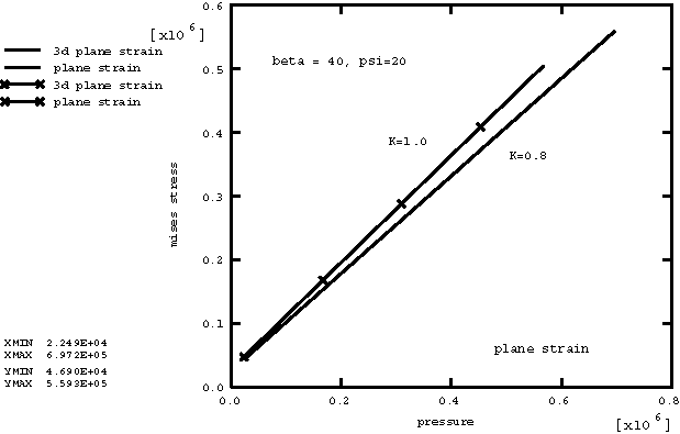
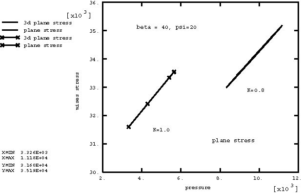
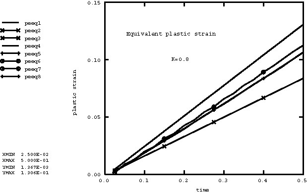
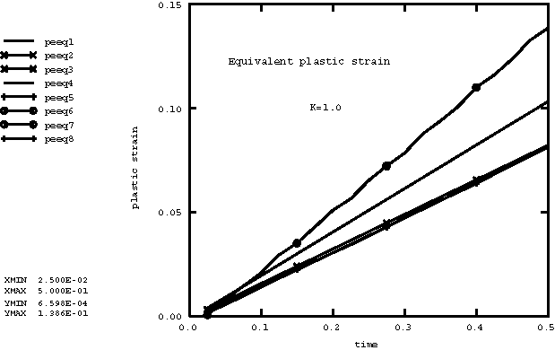
This is accomplished as described below. In rows (a) and (c) in Figure 1 the bottom and top nodes of each element are given equal and opposite prescribed constant velocities in the y-direction to generate a compressive loading. For rows (b) and (d) in Figure 1 the top nodes of each element are given prescribed velocities in the x-direction, while the bottom nodes are fixed, thereby leading to simple shear modes. The elements in rows (a) and (c) in Figure 1 are assigned material definitions with an associated flow rule: the friction angle () and dilation angle () are each 40°. The elements in rows (b) and (d) in Figure 1 are assigned material definitions with a nonassociated flow rule: the friction angle () is 40°, while the dilation angle () is 20°. The value of K is a measure of the strength differences in tension and compression. The yield surface will not be circular in the deviatoric stress space if K does not have a value of 1.0. In the first two rows of elements in Figure 1 a value of 0.8 is assigned. In rows (c) and (d) in Figure 1 a value of 1.0 is assigned to the elements. The plastic stress-strain relationship is defined using the extended Drucker-Prager plasticity model with hardening. Perfect plasticity is assumed, with the yield stress in uniaxial compression 40 × 103. The elastic properties are 20 × 106, 0.3. Material densities are 1000. Results and discussionFigure 2 shows the plot of Mises stresses versus pressure in the plane strain cases (elements C3D8 and CPE4R) with an associated flow rule. This demonstrates the pressure-dependent nature of the material. In the case of 1.0, the slope of the curve corresponds to the tangent of 40°. Figure 3 shows the plot of Mises stresses against pressure in the plane stress cases (elements C3D8 and CPS4R) with an associated flow rule. Figure 4 shows the plot of Mises stresses versus pressure in the plane strain cases (elements C3D8 and CPE4R) with a nonassociated flow rule. In the case of 1.0, the slope of the curve corresponds to the tangent of 40°. Figure 5 shows the plot of Mises stresses against pressure in the plane stress cases (elements C3D8 and CPS4R) with a nonassociated flow rule. When K is less than 1.0, the slope of the Mises stress versus pressure curve will be less than or equal to the frictional angle. This depends on the plastic strain path in the noncircular deviatoric space. Figure 6 contains eight curves of the time history response of equivalent plastic strain for the eight elements that have a value of 0.8. Figure 7 contains eight history curves of equivalent plastic strain for the eight elements that have a value of 1.0. Only four curves are visible in Figure 6 and Figure 7 because the three-dimensional results for the C3D8R elements reproduce the plane strain and plane stress results. As discussed above, boundary conditions were applied to the C3D8R elements to achieve this correspondence. This serves as a check that both the two- and three-dimensional material models achieve the same results. The results that are obtained with Abaqus/Explicit are the same as those obtained with Abaqus/Standard. Input files
Figures       | |||||||