Simple load tests
Elements tested
FRAME2D
FRAME3D
Features tested
The elastic behavior of frame elements is tested. The different cross-sections considered for the frame elements are:
rectangular hollow box section
solid circular section
general cross-section
I-beam section
hollow circular section
solid rectangular section
The tests are performed for the following load conditions:
concentrated loads
gravity loads
force per unit length in the global and the local frame directions
thermal loads as nodal temperatures
transverse fluid drag load
fluid drag force on the ends of the frame
tangential fluid drag load
buoyancy load (closed-end condition)
transverse wind drag load
wind drag force on the ends of the frame
foundation loads in the global and local frame directions
These loads are considered to act either individually or in combination. Both regular static steps and linear perturbation steps are considered.
The local coordinate system is also tested. Temperature dependence of frame element properties is tested under thermal loading. The initial stress conditions and the initial temperature at the nodes are also verified.
Problem description
The problem consists of a cantilever with a length of 75.0 units made of five frame elements. Various orientations of the cantilever in space are considered. The cross-sectional dimensions shown in Verification of beam elements and section types are used for the five section types (rectangular hollow box, solid circular, hollow circular, rectangular, and I-beam).
The cantilever is subjected to concentrated tip loading that leads to both flexure and torsion. The wind loads, WD1 and WD2, and the Aqua loads, FD1 and FD2, also apply concentrated forces at the nodes. The remaining loads cause uniformly distributed loading on the cantilever. Under thermal loading the free end of the cantilever is fixed. The wind velocity profile is made nearly uniform with the height by setting the exponent to 1 × 10.0−9. The fluid velocity in the Aqua loading is constant with height. With foundation loads the boundary conditions of the cantilever are changed to simple supports, and the cantilever is pressed uniformly into the foundation using distributed loads.
Material:
| Young's modulus at temperature −10.0 units: | 3 × 10⁶ |
| Poisson's ratio at temperature −10.0 units: | 0.3 |
| Young's modulus at temperature 90.0 units: | 1.5 × 10⁶ |
| Poisson's ratio at temperature 90.0 units: | 0.3 |
| Reference temperature for definition of thermal expansion coefficient: | −10.0 |
| Thermal expansion coefficient at −10.0 temperature: | 0.001 |
| Thermal expansion coefficient at 90.0 temperature: | 0.002 |
| Initial temperature: | −10.0 |
| Material density: | 0.8 |
| Gravitational constant: | 10.0 |
| Density of air for wind loads: | 0.008 |
| Density of fluid for Aqua loads: | 0.008 |
| Seabed level: | −100.0 |
| Still fluid level: | 50.0 |
| Foundation stiffness: | 1500.0 |
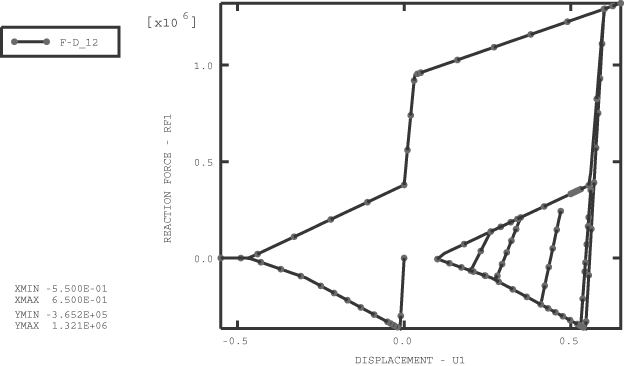
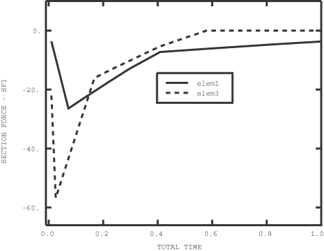
Results and discussion
The problem is statically determinate. The section forces and section strains match the analytical values.
Input files
- frame2d_bs_thermal.inp
Box section with thermal loading.
- frame2d_cs_wind_transform.inp
Circular section with wind loading and TRANSFORM.
- frame2d_gs_foundation.inp
General section with FOUNDATION loading.
- frame2d_gs_sig0.inp
General section with initial stress, perturbation step with LOAD CASE.
- frame2d_is_aqua.inp
I-section with Aqua fluid loading.
- frame2d_ps_sig0.inp
Pipe section with initial stress.
- frame2d_rs_aqua.inp
Rectangular section with Aqua fluid loading.
- frame2d_rs_aqua_transform.inp
Rectangular section with Aqua fluid loading and TRANSFORM.
- frame2d_rs_foundation.inp
Rectangular section with FOUNDATION loading.
- frame3d_bs_wind.inp
Box section with wind loading.
- frame3d_cs_foundation.inp
Circular section with FOUNDATION loading.
- frame3d_cs_transform.inp
Circular section with TRANSFORM.
- frame3d_gs_sig0_transform.inp
General section with initial stress.
- frame3d_is_aqua.inp
I-section with Aqua fluid loading.
- frame3d_ps_foundation.inp
Pipe section with FOUNDATION loading.
- frame3d_ps_thermal.inp
Pipe section with thermal loading.
- frame3d_rs_sig0_transform.inp
Rectangular section with initial stress and TRANSFORM.