Elements tested
C3D8R
CPE4R
CPS4R
ProductsAbaqus/Explicit Elements testedC3D8R CPE4R CPS4R Features testedPorous plasticity model. Problem descriptionThis problem contains 16 one-element verification problems that are all run in one input file. The purpose of this example is to test the porous plasticity model. Three different element types are tested (C3D8R, CPE4R, CPS4R). Figure 1 shows the 16 elements used in the analysis in their original and deformed shapes. The dashed lines represent the original mesh. The 8-node brick element (C3D8R) appears twice in each row: in one case boundary conditions are applied to constrain the out-of-plane displacement so that the C3D8R element simulates plane strain conditions, and in the second case no out-of-plane displacement boundary conditions are specified so that the C3D8R element simulates plane stress conditions. The original length of each side of the elements is 1. This example problem is designed to test the following features:
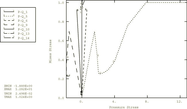
This is accomplished as described below. The loading on the elements in row (a) represents uniaxial tensile loading in the x-direction. In rows (b) and (c) in Figure 1 the left and right, top and bottom nodes of each element are given equal and opposite prescribed constant velocities in the x- and y-directions to generate biaxial compressive and tensile loading for both plane strain and plane stress cases. In row (d) in Figure 1 the bottom and top nodes of each element are given equal and opposite prescribed constant velocities in the x-direction to generate a simple shear loading. The elements in rows (b), (c), and (d) of Figure 1 are assigned material definitions with no void nucleation and with the coefficients 1.0. The behavior of the matrix material is assumed to be perfectly plastic with a yield stress 1.0. The elements in row (a) of Figure 1 are assigned material definitions with void nucleation ( 0.3, 0.1, 0.04) and with coefficients 1.5, 1.0, 2.25. The behavior for this matrix material includes hardening. The elastic properties are 300, 0.3, and a density of 0.001 is used in both material definitions. The initial relative density is assumed to be 0.95 in all cases. Results and discussionThe results obtained from the plane strain and plane stress elements in all the tests are identical to the corresponding results obtained from the three-dimensional elements where plane strain and plane stress boundary conditions are applied. The names of the individual curves that appear in the graph legend are a concatenation of the output variable names, an underscore (_), and a number. The number refers to the element number. For example, PEEQ–Q_1 refers to the Mises stress versus equivalent plastic strain curve for element 1. Figure 2 shows the variation of the volume fraction of voids as a function of time. The figure indicates that the void volume fraction remains constant during pure shear (line 1). In the compression test the void volume fraction reduces as the pressure increases (lines 2 and 3). Once the voids are fully closed, the material becomes almost incompressible. In the multiaxial and uniaxial tension tests the voids grow (lines 4 through 7) and new voids may nucleate (lines 6 and 7) for the material where void nucleation is specified. Figure 3 and Figure 4 show the variation of Mises stress with pressure stress and the variation of Mises stress with equivalent plastic strain. The evolution of the stress path of a material point is depicted through these figures. The influence of void closure and void growth on the pressure stress is shown in Figure 5. The figure contains the results obtained from the plane strain biaxial compression (line 1) and tension (line 2) tests. In the compression test the response is elastic, followed by plastic hardening until voids are closed, which is finally followed by incompressible behavior. In tension elastic behavior is followed by softening as voids grow. The results that are obtained with Abaqus/Explicit are the same as those obtained in Abaqus/Standard. Input files
Figures     | |||||||