Elements tested
B22
B32
B33H
MASS
S4R
SPRING1
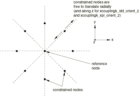
ProductsAbaqus/Standard Elements testedB22 B32 B33H MASS S4R SPRING1 Features testedVarious types of kinematic coupling connections are tested by selectively constraining degrees of freedom. Where tests are equivalent to existing multi-point constraint tests, references to those verification tests are made. Refer to Multi-point constraints for details of these tests. Problem descriptionProblems xkcbeam.inp and xkcbem3.inp impose beam constraints using kinematic coupling constraints and are the same as the equivalent MPC problem. Problem xkcrevo.inp tests the finite-rotation revolute behavior of the kinematic coupling when only two rotational degrees of freedom are constrained. Problem xkcuniv.inp tests the finite-rotation universal behavior of the kinematic coupling when only one rotational degree of freedom is constrained. The geometry for problems xkccirc.inp and xkccirc2.inp is shown in Figure 1.  In this test the center node is the kinematic coupling reference node, and the perimeter nodes are the coupling nodes. To verify the options for specifying local coordinate systems at these coupling nodes, the constraint shown is created using four separate kinematic coupling definitions that share the center reference node. Each of these coupling definitions defines the local coordinate system using a different orientation system: cylindrical, rectangular, spherical, and a system defined in user subroutine ORIENT. In all cases the resulting local constraint basis directions coincide with the local directions of a cylindrical coordinate system whose axis is normal to the plane containing the nodes and passes through the reference node. Problem xkccirc.inp also includes nodal transformations at some nodes; this will have no effect on the constraints. In the case of xkccirc.inp the kinematic coupling constrains all but the radial degree of freedom at the constrained nodes. Linear springs to ground (SPRING1) are attached to all constrained nodes and act in the x-direction. The reference node is then rotated about z during a static step. In the case of xkccirc2.inp the kinematic coupling constrains the circumferential degree of freedom only. Linear springs to ground (SPRING1) are attached to all constrained nodes and act in the x- and z-directions. The reference node is then rotated about x during a static step. Problem xkcsort.inp consists of a model composed of an axial arrangement of 20 shell elements. These elements are tied together using combinations of kinematic coupling constraints as well as MPCs. The constraints are defined such that kinematic coupling reference nodes appear after constraint definitions that eliminate degrees of freedom on these nodes; thus, sorting is required. The structure is clamped on one end and a concentrated axial load is applied to the other end. Results and discussionThe tests with equivalent MPC verification problems result in identical behavior. Tests xkcrevo.inp and xkcuniv.inp result in behavior that is identical to that of the equivalent revolute and universal MPCs. Tests xkccirc.inp and xkccirc2.inp result in motion of the constrained nodes, under action of the linear springs, as the reference node rotates. For test xkccirc.inp this motion remains on the local radius passing through the node at all increments. For test xkccirc2.inp this motion remains in the plane defined by the original configuration local radius and global z-direction as this plane rotates according to the motion prescribed at the reference node. Test xkcsort.inp results in an internal sorting of MPC and kinematic coupling definitions so that a proper elimination order is achieved. Input files
| |||||||