Elements tested
B21
B22
B31
B32
C3D8
C3D8I
C3D8R
CPE4R
CPS4R
CAX4R
M3D4R
PIPE21
PIPE31
S4
S4R
S4RS
S4RSW
SAX1
T2D2
T3D2
ProductsAbaqus/Explicit Elements testedB21 B22 B31 B32 C3D8 C3D8I C3D8R CPE4R CPS4R CAX4R M3D4R PIPE21 PIPE31 S4 S4R S4RS S4RSW SAX1 T2D2 T3D2 Features testedThe small-displacement deformation theory. Problem descriptionThis verification test consists of a set of single-element models for each element type in analyses that use the small-displacement theory. All degrees of freedom are prescribed so that the results do not include any dynamic effects. Each element is subjected to all applicable fundamental modes of deformation. The total strains are large to show that the results are linear and remain unaffected by changes to the element's current configuration. The material is linear elastic with a Young's modulus of 1.0 × 10⁵, Poisson's ratio of .33, and density of 1000. Results and discussionAll element types tested yield the appropriate results for their applicable fundamental modes of deformation. Results for the two-dimensional truss element are illustrated here. There are two global modes of deformation for a two-dimensional truss: longitudinal and lateral. The longitudinal mode is driven by fixing one end of the truss and prescribing a longitudinal displacement at the other. The axial stresses in the truss element as a result of longitudinal deformation for both small-displacement theory (geometric nonlinearities are neglected) and large-displacement theory (geometric nonlinearities are considered in the step) are shown in Figure 1. As the strains become large, the results diverge because the large-displacement theory accounts for the thinning of the truss as it stretches. The global lateral mode is invoked by prescribing a lateral displacement at one end of the truss element while holding all other degrees of freedom fixed. Results for the lateral case are shown in Figure 2. The nonlinear geometric effect is accounted for only in the large-displacement analysis. The small-displacement analysis ignores the extension of the truss due to its rotation and, therefore, sees no extensional strain due to the prescribed lateral displacements. Input files
Figures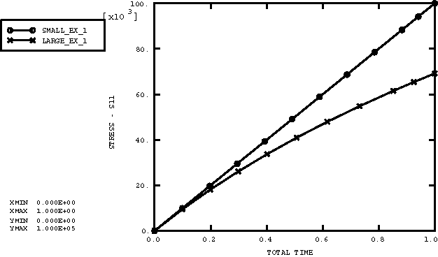 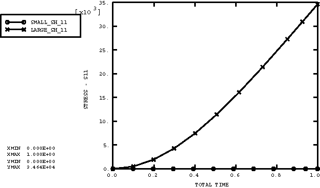 | |||||||