Elements tested
WARP2D3
WARP2D4
WARPF2D3
WARPF2D4
WARPF2D6
WARPF2D8
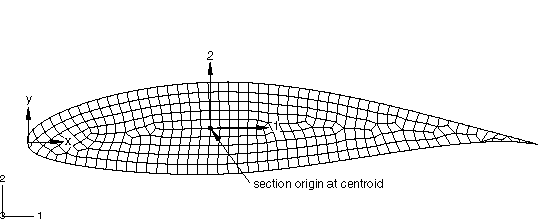
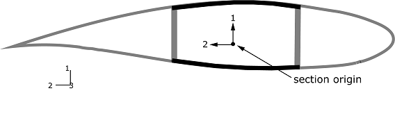
ProductsAbaqus/Standard Elements testedWARP2D3 WARP2D4 WARPF2D3 WARPF2D4 WARPF2D6 WARPF2D8 Features testedThe special-purpose two-dimensional elements WARP2D3 (3-node triangular), WARP2D4 (4-node quadrilateral), WARPF2D3 (3-node triangular), WARPF2D4 (4-node quadrilateral), WARPF2D6 (6-node triangular), and WARPF2D8 (8-node quadrilateral) are used to create two-dimensional beam cross-section models. The beam section generation procedure is used to numerically calculate the geometric, stiffness, and inertia properties of the section, including warping functions and the locations of the elastic and shear center (see Meshed beam cross-sections). The calculated properties are written to the jobname.bsp text file. Problem descriptionModel:Several cross-section shapes are considered. Two-dimensional finite element models of an I-section, an I-section with nodal offset, a rectangular section, a pipe section with a cut, a C-section, an airfoil section (see Figure 1), and a wind turbine rotor blade section (see Figure 2) are included.   Geometry from the National Renewable Energy Laboratory, a national laboratory of the U.S. Department of Energy. Mesh:There are two sets of element types that cannot be mixed in the same mesh. Elements of type WARP2D3 and WARP2D4 have one degree of freedom per node for the out-of-plane warping displacement for a unit twist of an associated beam element. Elements of type WARPF2D3, WARPF2D4, WARPF2D6, and WARPF2D8 have three degrees of freedom per node for the in-plane and out-of-plane warping displacements for a unit beam element section force or section moment. The cross-sections use only one set of element types. Material:Only elastic materials, using either linear isotropic or orthotropic shear behavior, can be used for two-dimensional models with 1-DOF warping elements. For two-dimensional models with 3-DOF warping elements, all linear elastic materials available for three-dimensional solid elements can be used (isotropic, orthotropic, and fully anisotropic elasticity). Boundary conditions:Boundary conditions are not meaningful when generating beam section properties and are ignored. Loading:Loads are not meaningful when generating beam section properties and are ignored. Results and discussionFor cross-sections with 1-DOF warping elements and 3-DOF warping elements and isotropic material, the beam cross-section properties for each of the meshed cross-sections are written to the jobname.bsp text file if the directional coupling in the beam element response to stretching, shearing, bending, and twisting can be fully characterized by the elastic center and shear center locations. In all cases, the beam cross-section properties are reported in the jobname.dat file. For cross-sections with 3-DOF warping elements, the properties and the warping functions are also written to a jobname.fbi binary file. The integrated values of the properties for the meshed beam cross-sections are compared to the analytical solutions or solutions generated for a section from the predefined library. The warping function shapes of the two-dimensional cross-sections compare well with the solutions for the solid element models of the beam subjected to a unit twist in the case of cross-sections with 1-DOF warping elements or subjected to the six unit section forces and moments in the case of cross-sections with 3-DOF warping elements. Input files
| |||||||