Verification of scaled mass matrices
Elements tested
- B21
- B22
- B31
- B32
- C3D4
- C3D6
- C3D8R
- CAX3
- CAX4R
- CPE3
- CPE4R
- CPS3
- CPS4R
- M3D3
- M3D4R
- MASS
- R2D2
- R3D3
- R3D4
- RAX2
- ROTARYI
- S3R
- S4R
- SAX1
- T2D2
- T3D2
Problem description
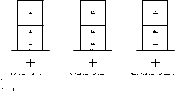
These problems verify that the element mass matrices are generated properly for every element type that can be scaled. Several element types are tested in each input file. For each element type an element pair consisting of a reference element and test element with identical geometries is defined. The material properties of each element pair are identical with the exception of the densities. The densities of the test elements are scaled with the FACTOR parameter so that in the analysis their element mass matrices are identical to those of the reference elements. Each element pair is subject to equivalent displacements (and rotations in the case of beams and shells) such that their response is dynamic. Rebars are included for every element type that permits the inclusion of rebar. Tests of membranes and shells are performed with and without nodal values specified with nodal thickness. Reaction forces for constrained nodes of each pair of elements are output for comparison purposes.
Results and discussion
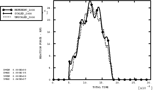
Reaction force histories for nodes on each pair of test and reference elements are nearly identical. Slight differences exist because the bulk viscosity is based on the unscaled mass during the first increment. Every increment thereafter, the bulk viscosity is based on the scaled mass.
Input files
- mscale_continuum.inp
-
Two-dimensional and three-dimensional continuum elements.
- mscale_beamshell.inp
-
Two-dimensional and three-dimensional beams and shells.
- mscale_special.inp
-
Elements with mass but no stable time increment.