Elements tested
R3D4
S4R
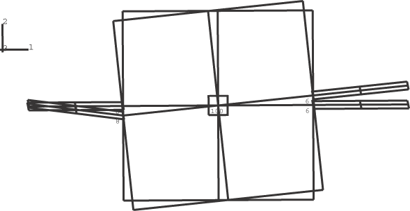
ProductsAbaqus/StandardAbaqus/Explicit Elements testedR3D4 S4R Features testedUse of TIE NSET and PIN NSET to define connections between rigid bodies and deformable elements. Problem descriptionA square rigid sheet is connected by one node at each of two opposite edges to deformable rectangular plates consisting of S4R elements. The connection to the first plate at node 6 of the rigid body is assumed to be a tie connection where it is desired to transmit moment and rotation. The connection to the second plate at node 8 is assumed to be a pin connection. A moment of magnitude 1000 is applied to the rigid body reference node about the global z-axis. A ROTARYI element with 10 is attached to the rigid body reference node. Two representations for the square rigid sheet are considered:
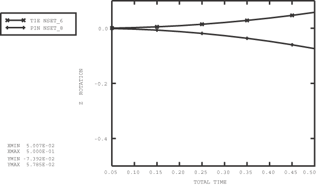
Results and discussionThe original and final configurations for Cases 1 and 2 are shown in Figure 1 and Figure 2. It is clear from the results that at tie connections the plate rotates with the rigid body since there is transfer of moment from the rigid sheet to the rectangular plate at the connecting node. At pin connections moments are not transferred at the connecting node since the rigid body at the connecting node has only translational degrees of freedom. This results in large relative motions between the rigid sheet and the deformable plate at the pin nodes. Figure 3 shows the angular rotation about the z-axis at the connecting nodes for Case 1. The angular rotation at the pin node, node 8, is negative in response to the applied positive moment, which is the physically intuitive result. Input filesAbaqus/Standard analysis
Abaqus/Explicit analysis
Figures   | |||||||