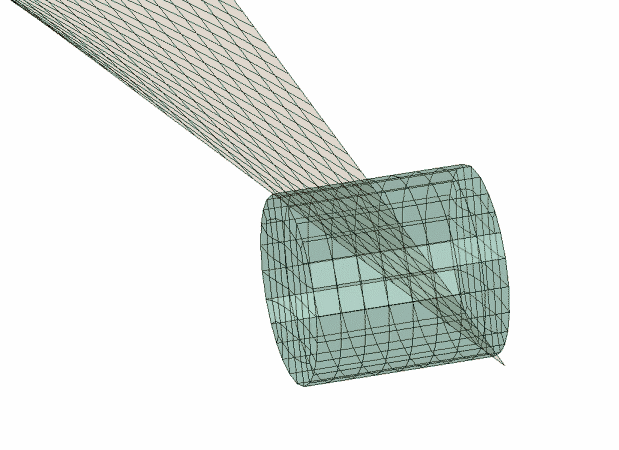
This verification problem tests the ability of PC3D elements to describe the impact of a bird on an airplane engine
blade. The rotating airplane engine blade is subjected to an impact with a
cylindrical model of a flying bird using the smoothed particle hydrodynamic
(SPH) technique. After the impact, the bird
completely disintegrates and splashes over the surface of the engine blade. A
similar approach can be used for modeling severe deformations of thin shell
structures impacted by objects moving with high velocity.
Model:
This model analyzes the impact interaction between a flying object and a
rotating airplane engine blade. The airplane engine blade is modeled using 960 S4RS shell elements. A set of nodes closer to the turbine hub are
kinematically coupled to a reference node situated at the center of the hub. A
constant angular velocity of
rad/s is applied at the reference node about the z-axis.
The engine blade is modeled with an elastic-plastic material with Young's
modulus
GPa, Poisson's ratio ,
density
kg/m3, and isotropic hardening. The flying bird is modeled using
4160 PC3D elements. The bird material is modeled using a tabular equation
of state (EOS) material with a tensile failure
strength of 94 MPa and a density of
kg/m3. The radius of the cross-section of the cylinder modeling the
bird is 0.04 m, and the height of the cylinder is 0.076 m. The contact
interaction between the surfaces of the bird object and the shell structure is
defined through contact inclusions.
The initial configuration of the model is shown in
Figure 1.
An intermediate deformed configuration of the airplane engine blade and the
bird system is shown in
Figure 2.
Results and discussion
After the impact, the blade undergoes severe deformation. The edges of the
thin shell structure close to the impact area become warped. The bird object
completely disintegrates and splashes over the surface of the engine blade.
This test problem verifies the capability of the
SPH technique to model large deformations and
failure of fluid-like materials. Contact interaction between the PC3D and the S4RS elements is also verified.
Figure 1. Undeformed configuration of the airplane engine blade and the bird
system. Figure 2. Deformed configuration of the airplane engine blade and the bird
system.
Bird strike on an airplane engine blade using conversion
Elements tested
C3D8R
PC3D
Problem description
This verification problem tests the ability of reduced-integration continuum
elements (C3D8R) elements to convert to SPH
particles as deformation progresses during the impact of a bird on an airplane
engine blade.
Model:
Overall the model, the material properties, and the loading conditions are
the same as in
Bird strike on an airplane engine blade.
The only exception is that the bird is first modeled with C3D8R elements rather than with PC3D elements. A strain-based criterion is used to convert each
continuum element to eight SPH particles. The
contact interaction between the internally generated particles and the shell
structure is defined automatically from the user-defined contact inclusions.
The initial configuration of the model is shown in
Figure 3.
An intermediate deformed configuration of the airplane engine blade and the
bird system is shown in
Figure 4.
Results and discussion
After the impact, the blade undergoes severe deformation. Continuum elements
convert progressively as the specified maximum principal strain is reached in
each element. The edges of the thin shell structure near the impact area become
warped.
Figure 3. Undeformed configuration of the airplane engine blade and the bird
modeled with continuum elements. Figure 4. Deformed configuration of the airplane engine blade and the bird as
the conversion of the continuum elements progresses.
Water splash in a square pan
Elements tested
PC3D
Problem description
This problem tests the ability of PC3D elements to model impact and mixing of two liquid bodies of the
same material. A spherical water drop falls into a square container containing
water under gravitational forces. The water drop moves down toward the water in
the container and, after splashing, settles to an equilibrium state within the
container. The container is modeled using five shell elements. In this test
problem mass scaling and bulk modulus reduction are used to increase the value
of the stable time increment. Since compressibility does not play a significant
role in this analysis, this modeling choice should not affect the results
significantly.
Model:
This model analyzes the impact and mixing of two liquids with the same
material properties. The spherical liquid drop and the liquid in the container
are modeled using 3544 and 9000 PC3D elements, respectively. Both liquids are defined using an
EOS material of type USUP modeling a linear equation of state. The parameters used in
this material model are
mm/s, ,
and .
To increase the stable time increment, the density of the liquid is
artificially defined as 1
tonne/mm3. The height of the container is 5 mm. The horizontal
cross-section of the container has a square shape with a side length of 15 mm.
The lateral and bottom walls of the container are modeled as S4R shell elements. The contact interaction between the liquid and
the shell structure is defined through contact inclusions.
The initial configuration and an intermediate configuration are shown in
Figure 5
and
Figure 6.
Results and discussion
This test problem verifies the capability of the
SPH technique in
Abaqus/Explicit
to model the impact and mixing processes of two liquid materials. The mass
scaling technique, which drastically increases the stable time increment in
this dynamic analysis, is also verified.
Figure 5. The initial configuration of a water drop and a water-filled square
pan. Figure 6. An intermediate configuration of the water drop splashing in a
water-filled square pan.
Splashing of a figurehead
Problem description
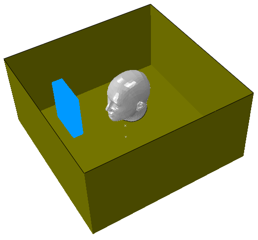
This problem tests the impact interaction between PC3D elements and a rigid solid structure with a complex curved
surface. A block of liquid is moved toward a figurehead and splashes over its
surface. The cohesion force used in this model helps maintain some tensile
strength for the liquid material during splashing.
Model:
This model analyzes the impact interaction between a liquid modeled using
the SPH technique and a rigid solid structure.
The block of liquid is modeled using 53040 PC3D elements. The material model of the liquid used is an
EOS material of type USUP modeling a linear equation of state. The material parameters
used are
mm/s, ,
and .
A failure strength of 2 MPa is defined for this
EOS type material. To model the figurehead,
4084 R3D3 rigid elements are used. The initial velocity of the liquid is
3000 mm/s along the y-direction toward the figurehead. The
confining box has a dimension of 800 mm × 800 mm × 500 mm, and it is modeled
using 48 R3D4 rigid elements. The contact interaction between the liquid and
the surfaces of the figurehead and the confining box is defined through contact
inclusions with the no-friction surface interaction.
The initial and intermediate configurations are shown in
Figure 7
and
Figure 8.
Results and discussion
This problem verifies the capability of the
SPH technique to model the impact interaction
between a block of liquid and a rigid body with a complex surface topography.
The effects of the cohesion force modeled for the
SPH particles are also tested.
Figure 7. The initial configuration of a block of water and a
figurehead. Figure 8. An intermediate configuration of water splashing on a
figurehead.
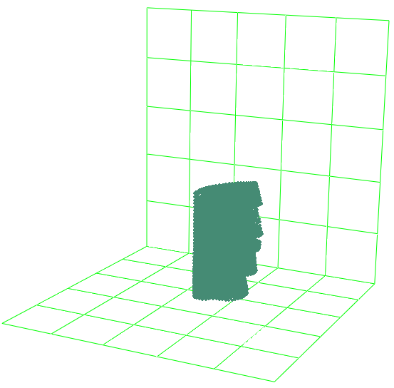
Melting of a figurehead statue
Problem description
This problem tests the ability of PC3D elements to model large deformation and failure of an isotropic
elastic-plastic material upon an abrupt change of temperature. A figurehead
statue, modeled with temperature-dependent material properties, begins to melt
as the temperature suddenly jumps to a higher value. The contact interaction
between the SPH related particles and the
rigid elements is also tested.
Model:
This problem analyzes the temperature-related failure of a figurehead statue
modeled using the SPH technique. The
figurehead statue is modeled using 8252 PC3D elements, and it is characterized by a temperature-dependent
elastic-plastic material mode via field variable dependencies. The Young's
modulus, ,
is equal to 2 MPa when the non-dimensional field variable is equal to 1.0, and
it is equal to 0.8 MPa when this variable changes to 2.0. The dependence of the
plastic properties on the temperature is given via tabular data. The density of
the material is defined as
tonne/mm3. Fifty R3D4 elements are used to model the bottom and the lateral walls. The
melting process of the figurehead statue is accelerated after a sudden rise of
the temperature during the dynamic analysis. The contact interaction between
the solid statue and the rigid wall is defined through contact inclusions.
The initial and intermediate configurations are shown in
Figure 9
and
Figure 10.
Results and discussion
This problem verifies the application of the
SPH technique to model the large deformation
and failure of a temperature-dependent isotropic elastic-plastic material. The
contact interaction between this material modeled using
SPH particles and the rigid bodies is also
tested.
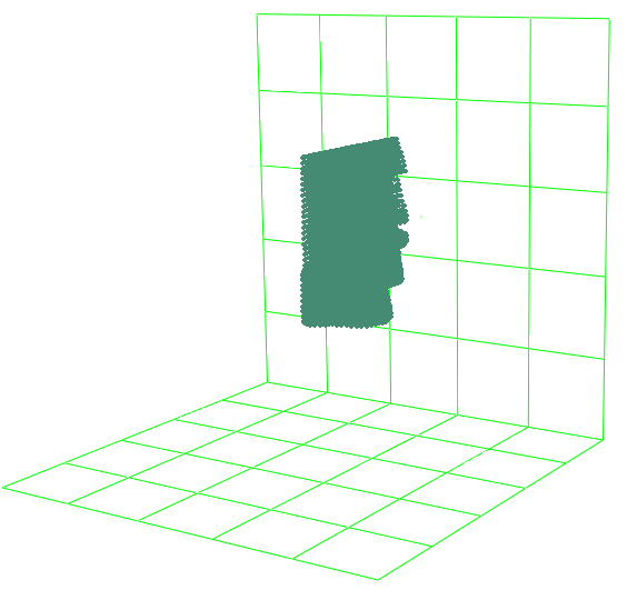
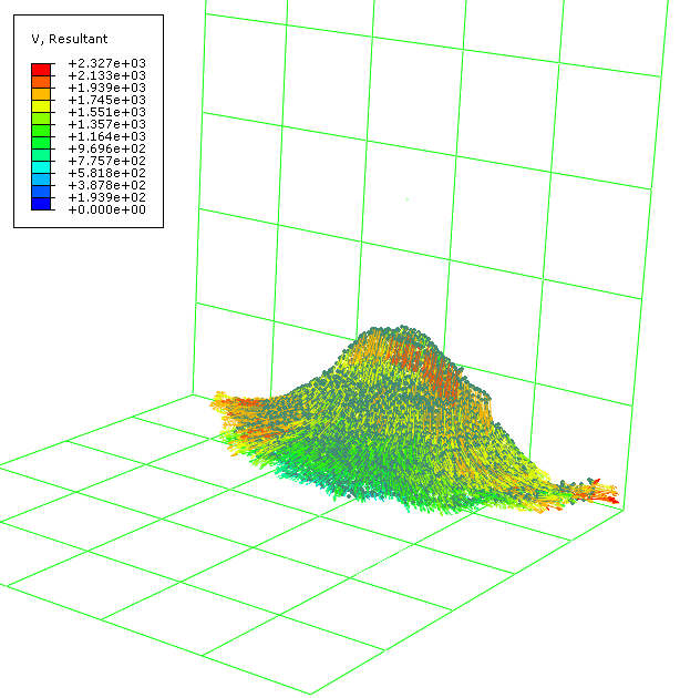
Figure 9. The initial configuration of the figurehead statue. Figure 10. Velocity vector plot of an intermediate configuration for the melted
figurehead statue.
Smashing of a figurehead
Problem description
This problem tests the ability of PC3D elements to model the impact of a figurehead on solid walls. The
figurehead, modeled as a toothpaste-like viscous material, is smashed onto
solid walls. After the impact, the figurehead is completely crashed on the
lateral wall and then flows down onto the bottom wall under gravitational
forces. The contact interaction between the
SPH related particles and the rigid elements
is also tested.
Model:
This model analyzes the impact interaction between a figurehead and solid
walls. The figurehead is modeled using 8252 PC3D elements. The material model used for this figurehead is an
EOS material of type USUP modeling a linear equation of state. The material parameters
used are ,
,
and .
A linear viscous shear behavior is defined for this hydrodynamic material
through tabular data. A tensile failure strength of 10 MPa is also defined for
this material. The density of the figurehead is set to
tonne/mm3. Fifty R3D4 elements are used to model the bottom and the lateral walls. The
initial velocity of the figurehead is set to 1.0
mm/s toward the lateral wall. The figurehead then follows a parabolic path
under gravitational forces until it strikes the wall. After the impact, the
figurehead is smashed onto the lateral wall and then crashes into the corner
edge because of complete material failure. The contact interaction between the
figurehead and the rigid wall is defined through contact inclusions using rough
friction to describe the frictional interactions.
The initial configuration and an intermediate configuration of the
figurehead and the rigid walls are shown in
Figure 11
and
Figure 12.
Results and discussion
This problem verifies the application of the
SPH technique to model the failure of a
cohesive linear viscous material. The contact interaction between this material
and a rigid wall is also tested.
Figure 11. The initial configuration of a figurehead. Figure 12. Velocity vector plot of an intermediate configuration for the
figurehead after being smashed on a wall.
Projectile impact on a plate
Elements tested
PC3D
Problem description
This verification problem tests the ability of PC3D elements to handle large deformations and failure of a
rate-dependent elastic-plastic material upon impact of a high-speed projectile.
A solid plate, of which the central part is modeled using the
SPH technique, is subjected to an impact by a
high-velocity cylindrical rigid object. After the impact, the part close to the
center of the plate first undergoes a large deformation and then breaks apart.
Eventually, the projectile perforates the plate.
Model:
This model analyzes the impact interaction between a high-velocity
projectile and a solid plate. The solid plate has a dimension of 400 mm × 400
mm × 12 mm. A circular part with a radius of 100 mm in the center of the plate
is modeled using 102726 PC3D elements, and the remaining part of the plate is modeled using
9312 C3D8R elements. The length and radius of the cylindrical rigid solid
projectile are 25 mm and 8.4 mm, respectively. The initial speed of the
projectile is set to 1000 m/s. The material used for the plate is a steel with
Young's modulus
MPa, Poisson's ratio
0.3, and density
tonne/mm3. The plate is modeled as an elastic-plastic material with
rate-dependent hardening. Ductile and shear damage are evolved based on an
energy criterion. The interaction between the rigid projectile and the solid
plate is defined using frictional contact with a friction coefficient of 0.3.
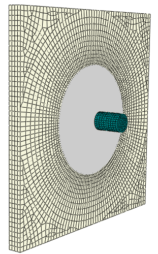
The initial configuration of the model is shown in
Figure 13,
and an intermediate deformed configuration cross-section is shown in
Figure 14.
Results and discussion
After the impact, the center part of the plate first undergoes a large
deformation and then breaks into pieces. In the end, the projectile penetrates
the plate completely. This problem verifies the ability of the
SPH technique to model large deformation and
failure of rate-dependent elastic-plastic materials. Contact interaction
between the PC3D elements and solid elements is also verified.
Figure 13. The initial configuration of the solid plate and projectile. Figure 14. Contour plot of Mises stress for the solid plate subjected to an
impact of a projectile.