Elements tested
- C3D8PH
- C3D8PT
- C3D10MP
- C3D20P
- C3D20RP
- CAX4RP
- CAX6MP
- CAX8P
- CAX8RP
- CPE4P
- CPE6MP
- CPE8P
- CPE8RP
ProductsAbaqus/Standard Elements tested
Features testedThe submodeling capability is applied to two-dimensional, three-dimensional and axisymmetric continuum elements with pore pressure. General steps invoking the soils consolidation procedure are used for both the global and submodel analyses. Problem descriptionModel:All global models have dimensions 3.0 × 5.0 in the x–y or r–z plane. Each submodel has dimensions 2.05 × 3.45 in the x–y or r–z plane and occupies the lower right-hand corner of the corresponding global model. In all but the axisymmetric models, the out-of-plane dimension is 1.0. In axisymmetric models the structure analyzed is a hollow cylinder with outer radius 5.0. Material:
Loading:In all models, a distributed flow of magnitude 0.002 is applied to the right face, where the sink pore pressure is 14.7. Boundary and initial conditionsIn the global model, fixed boundary conditions = 0 and = 0 are prescribed on the left and bottom faces, respectively. In three-dimensional models the additional constraints = 0 are applied to the nodes on the front and back faces. The initial void ratio is unity everywhere and fixed pore pressure boundary conditions are applied on the left face. In the submodel, = 0 is prescribed everywhere on the bottom face, while degrees of freedom 1, 2 and 8 for the nodes on the top and left faces are being driven by the global solution. Results and discussionIn the global analyses, the pore pressure field predicted by Abaqus varies linearly in the x-direction in nonaxisymmetric models and logarithmically in the r-direction in axisymmetric models. The predicted displacement field is nonuniform in all models. These results are depicted in the pore pressure and x- or r-displacement contour plots shown below. For comparison purposes, the pore pressure and displacement solutions predicted by the submodels are also presented in the same contour plots and excellent agreement between global and submodel results is obtained. Hence, the amplitudes of all driven variables in the submodeled analysis are correctly identified in the global analysis file output and applied at the driven nodes in the submodel analysis. Global and submodel analyses results for 8-node plane strain elements are shown in Figure 1 and Figure 2. Global and submodel analyses results for 8-node axisymmetric elements are shown in Figure 3 and Figure 4. Global and submodel analyses results for 20-node brick elements (front face) are shown in Figure 5 and Figure 6. Input filesThe following input files test the transient soils consolidation procedure. Each test performs a single increment transient consolidation calculation for a time period of one.
Figures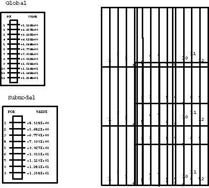  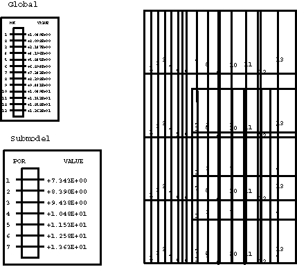 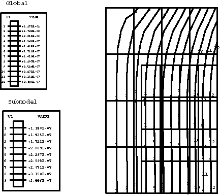 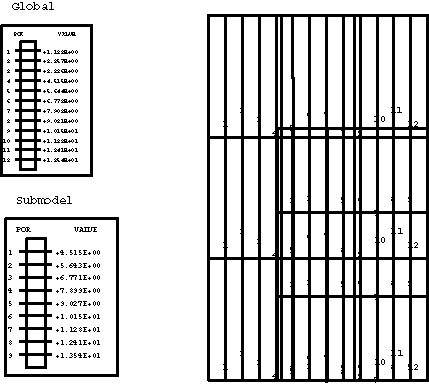 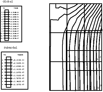 | |||||||||||||||