Elements tested
- DC1D2E
- DC1D3E
- DC2D3E
- DC2D4E
- DC2D6E
- DC2D8E
- DCAX3E
- DCAX4E
- DCAX6E
- DCAX8E
- DC3D4E
- DC3D6E
- DC3D8E
- DC3D10E
- DC3D15E
- DC3D20E
ProductsAbaqus/Standard Elements tested
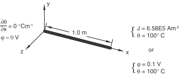
Problem descriptionThe problem illustrated in Figure 1 consists of a 1-m-long conductor through which a constant current density of 6.58E5 Am−2 is established by creating a potential difference across the ends of the conductor or by prescribing a concentrated current. The electrical energy generated by the flow of current is converted into heat, which results in a temperature distribution through the conductor. Only a steady-state solution is considered for each test. A reasonable mesh is used in each case to obtain the quadratic distribution of heat.  Material:Thermal conductivity = 45 W/m°C; electrical conductivity = 6.58E6 1/ m. Boundary conditions:Zero potential ( 0 V) and zero temperature gradient ( 0°Cm−1) at 0 m. Potential 0.1 V and temperature 100°C, or current density of 6.58E5 Am−2 and temperature 100°C at 1 m. With these boundary conditions the problem is one-dimensional. It is assumed that all electrical energy is converted into heat. Reference solutionIn this uniaxial problem the exact solution for the temperature is of the form , where , , and are real constants. Application of the above material properties and boundary conditions leads to the exact solution where −1462.2. Results and discussionThe tests are composed of three steps. In Step 1 the proper temperature boundary conditions are applied, and the flow of current is obtained by a potential difference between the two ends of the conductor. The coupled thermal-electrical procedure is used to obtain the desired temperature distribution across the conductor. For first-order elements the results are a function of y and z when the mesh generated is skewed in the x–y plane and/or the x–z plane. For the different test cases studied, the temperature may vary by as much as 3% in the y–z plane for a given x-value. Therefore, special care is needed when using triangular and tetrahedral elements. The exact solution is recovered in most test cases, with a maximum deviation of 1.5% from the exact solution observed with the DC3D6E elements. For second-order elements the exact results are obtained since the results are at most a quadratic function of the variable x. Moreover, skewed meshes do not affect the results. Step 2 is a heat transfer step in which the conductor is allowed to cool down. Step 3 invokes a coupled thermal-electrical procedure in which the same amount of electrical energy as that of Step 1 is provided to the specimen. However, energy is now supplied by specifying a prescribed current at 1 m instead of a potential of 0.1 V. Here again, the temperature results are identical to those obtained in Step 1, and the potential distribution that served as input for Step 1 is retrieved as output in this step. Input files
| |||||||